 简体中文
简体中文 English
 русский
 Español
Home / News / Industry News / How does the slot geometry of the Motor Stator Core (open, semi-closed, or closed slots) impact winding ease, harmonic distortion, and cogging torque?
How does the slot geometry of the Motor Stator Core (open, semi-closed, or closed slots) impact winding ease, harmonic distortion, and cogging torque?
The slot geometry of a Motor Stator Core is one of the most consequential design decisions in electric motor engineering. To answer directly: open slots offer the easiest winding access but generate the highest harmonic distortion and cogging torque; semi-closed slots provide the best balance across all three parameters; and closed slots minimize harmonics and cogging but significantly complicate the winding process. Understanding the trade-offs in depth allows engineers and procurement teams to select the right Motor Stator Core configuration for their specific application.
The Three Slot Types in a Motor Stator Core: A Structural Overview
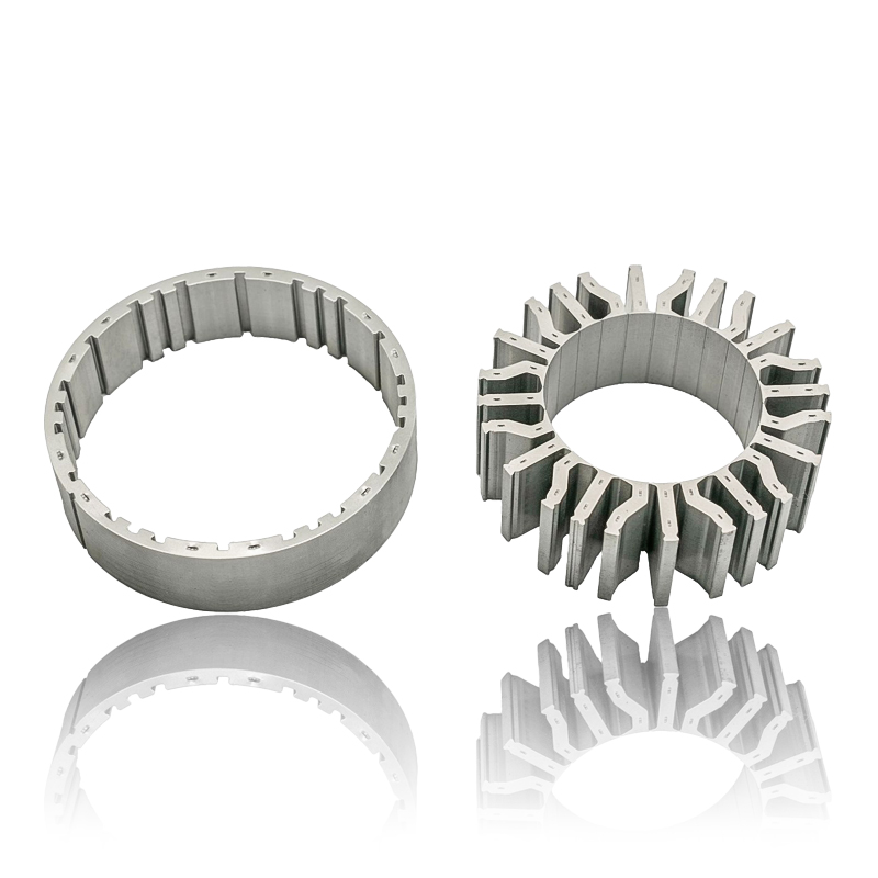
Before evaluating performance impacts, it is essential to understand what physically distinguishes each slot geometry in a Motor Stator Core:
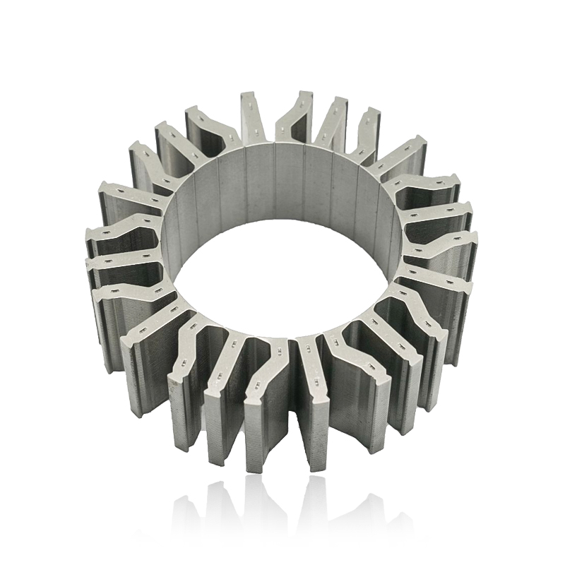
- Open slots have a fully exposed slot opening facing the air gap, typically with an opening width equal to or greater than the slot body width.
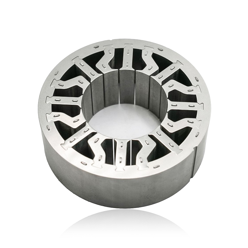
- Semi-closed slots have a narrow opening — usually between 2 mm and 5 mm — that is significantly smaller than the slot body, creating a partial bridge over the conductor area.
- Closed slots are fully enclosed by a thin magnetic bridge, with no direct air-gap exposure of the conductors. The bridge thickness typically ranges from 0.3 mm to 1.0 mm.
Each configuration alters the magnetic flux path, mechanical accessibility, and electromagnetic behavior of the Motor Stator Core in distinct and measurable ways.
Impact on Winding Ease: Practical Implications for Manufacturing
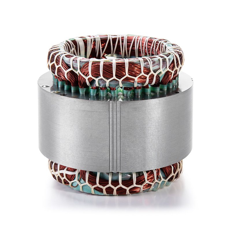
The slot opening width directly determines whether pre-wound coils, needle winders, or manual insertion techniques can be used when assembling a Motor Stator Core.
Open Slots
Open slots allow the insertion of pre-formed coils with rectangular cross-sections, enabling high copper fill factors — often exceeding 70%. This is the preferred geometry for medium- and high-voltage motors above 1 kV, where form-wound coils are standard. Automated coil insertion is straightforward, reducing assembly time and labor cost significantly.
Semi-Closed Slots
Semi-closed slots require needle winding or individual conductor insertion through the narrow opening. This limits conductor diameter and increases winding complexity. However, modern automated needle winders can achieve copper fill factors of 55–65% in semi-closed Motor Stator Core geometries, making them viable for mass production in fractional and integral horsepower motors.
Closed Slots
Closed slots present the greatest winding challenge. Conductors must either be threaded through before the stator laminations are stacked, or the magnetic bridge must be locally deformed after conductor insertion. Copper fill factors are typically limited to below 50%, and manufacturing yield rates can be lower. Closed-slot Motor Stator Cores are generally reserved for applications where electromagnetic performance overrides manufacturing convenience, such as high-speed spindle motors or low-noise servo drives.
| Slot Type | Winding Method | Typical Copper Fill Factor | Manufacturing Complexity |
|---|---|---|---|
| Open | Form-wound / coil insertion | > 70% | Low |
| Semi-Closed | Needle winding / wire insertion | 55–65% | Moderate |
| Closed | Pre-insertion / bridge deformation | < 50% | High |
Harmonic Distortion: How Slot Geometry Shapes the Air-Gap Flux
Harmonic distortion in a motor is largely caused by variations in the air-gap permeance — that is, irregularities in how easily magnetic flux crosses from the Motor Stator Core to the rotor. Slot openings act as permeance discontinuities, and their size directly governs the magnitude of flux harmonics.
In open-slot Motor Stator Core designs, the wide slot opening creates a pronounced permeance variation as the rotor moves past each slot. This generates significant slot harmonics — typically the (6k ± 1) order harmonics in three-phase machines — which increase total harmonic distortion (THD) in the back-EMF waveform. Measured THD values for open-slot configurations can reach 8–15% depending on slot pitch and rotor pole count.
Semi-closed slots reduce the permeance variation substantially. By narrowing the slot opening to 2–4 mm, the flux path becomes more uniform, and back-EMF THD values typically fall to 3–7%. This improvement directly reduces motor noise, bearing loads from magnetic forces, and losses in rotor conductors caused by harmonic-induced eddy currents.
Closed slots on the Motor Stator Core provide the most sinusoidal air-gap flux distribution, with back-EMF THD values often below 3%. The thin magnetic bridge maintains near-uniform permeance around the entire inner bore of the stator. However, the bridge itself can saturate at high flux densities, which partially limits this advantage at full-load operating points. Bridge saturation typically begins when the flux density in the bridge exceeds 1.8–2.0 T.
Cogging Torque: The Role of Slot Opening Width in Torque Ripple
Cogging torque — the pulsating torque produced by the magnetic attraction between rotor magnets and the stator teeth — is one of the most critical performance parameters influenced by Motor Stator Core slot geometry. It directly affects low-speed smoothness, positioning accuracy, and acoustic noise.
The fundamental cause of cogging torque is the variation in magnetic reluctance as the rotor poles align and misalign with stator teeth. A wider slot opening on the Motor Stator Core creates a sharper reluctance gradient, resulting in higher peak cogging torque values. In open-slot designs, cogging torque can represent 5–15% of rated torque, which is unacceptable in precision servo, robotics, or direct-drive applications.
Semi-closed Motor Stator Core slots reduce cogging torque to approximately 1–5% of rated torque by smoothing the reluctance transition. Combined with standard mitigation techniques such as rotor skewing (typically 1 slot pitch) or fractional slot-pole combinations, cogging torque in semi-closed designs can be reduced to levels below 1% of rated torque in well-optimized motors.
Closed-slot Motor Stator Cores deliver the lowest inherent cogging torque, often below 0.5% of rated torque, because the magnetic bridge eliminates the reluctance discontinuity at the slot opening entirely. This makes closed-slot designs the preferred choice for ultra-smooth drive applications such as medical equipment motors, precision CNC spindles, and high-fidelity audio turntable motors.
Application-Based Selection Guide for Motor Stator Core Slot Geometry
Choosing the correct slot geometry for a Motor Stator Core depends on the application's priority matrix. The following guidance reflects industry-proven practices:
- Industrial induction motors (general purpose): Semi-closed slots are standard. They balance manufacturing efficiency with acceptable harmonic performance under variable-frequency drive (VFD) operation.
- Medium- and high-voltage form-wound motors (above 1 kV): Open slots are necessary to accommodate pre-formed coils with adequate insulation thickness. Harmonic mitigation is handled via rotor design and external filters.
- Permanent magnet synchronous motors (PMSM) for servo and robotics: Semi-closed or closed slots are preferred, with closed slots chosen when cogging torque below 1% of rated torque is required.
- High-speed motors (above 10,000 RPM): Closed slots on the Motor Stator Core are favored to minimize rotor surface losses from harmonic flux components that would otherwise penetrate the rotor at high frequency.
- EV traction motors: Semi-closed slots with optimized tooth-tip geometry are most common, balancing NVH (noise, vibration, harshness) requirements with mass-production winding efficiency.
Additional Design Parameters That Interact With Slot Geometry
Slot geometry does not operate in isolation within a Motor Stator Core. Its impact on winding ease, harmonic distortion, and cogging torque is modulated by several interacting design variables:
- Slot count: A higher number of stator slots reduces the harmonic order spacing and generally lowers cogging torque amplitude. A 48-slot Motor Stator Core will typically exhibit lower cogging torque than an equivalent 24-slot design for the same pole count.
- Tooth-tip chamfer angle: Even in open-slot designs, chamfering the tooth tips at 30–45° can reduce the sharpness of the reluctance gradient and lower cogging torque by 20–40% without modifying the slot opening width.
- Lamination material grade: High-silicon electrical steel (e.g., M270-35A) in the Motor Stator Core reduces eddy current losses excited by harmonic flux components, making it especially valuable in open-slot designs where harmonics are inherently higher.
- Air-gap length: A larger air gap attenuates slot harmonic permeance variations, partially compensating for the effects of wider slot openings. However, increasing air gap also reduces power factor and requires higher magnetizing current.
Key Takeaways for Engineers and Buyers of Motor Stator Cores
When specifying or evaluating a Motor Stator Core, slot geometry must be treated as a primary design variable — not an afterthought. The following summary captures the essential decision criteria:
- Prioritize semi-closed slots for most industrial and consumer motor applications as the optimal trade-off between performance and manufacturability.
- Specify open slots only when the application demands high copper fill factors and uses form-wound coils, and where harmonic filtering is available.
- Select closed slots when cogging torque and harmonic distortion are the overriding concerns, and when the higher manufacturing cost of the Motor Stator Core is justified by end-application requirements.
- Always evaluate slot geometry in conjunction with rotor design, slot count, lamination grade, and drive electronics to achieve optimal system-level performance.
The well-chosen slot geometry in the Motor Stator Core is not merely an electromagnetic optimization — it is a direct lever on manufacturing cost, motor reliability, acoustic quality, and application suitability. Engineers who treat this parameter with the rigor it deserves will consistently deliver superior motor system outcomes.
Previous article
What are the weight and performance trade-offs between an aluminum composite and a silicon steel Automotive Small Motor Stator Core for lightweight EV applications?
next article
How is the insulation system of an Automotive Small Motor Stator Core rated for thermal performance in high-temperature underhood automotive environments?
Related News
-
What are Stator and Rotor Cores? Stator Cores A stator core is the stationary component of an electric motor. It's the part that houses the copper windings, which, when an electric current passes thro...
See Details -
Introduction The modern automobile is a complex machine, and its evolution has been driven by continuous innovation in every component. While internal combustion engines have dominated the industry fo...
See Details -
The Importance of Material Selection for Rotor and Stator Cores in Electric Vehicle Motors In the design of electric vehicle (EV) motors, material selection is a pivotal factor influencing the motor’s...
See Details -
Introduction of automotive motor stator and rotor cores The increasing popularity of electric vehicles and hybrid electric vehicles has brought about significant advancements in automotive technology....
See Details

Zhejiang Jufeng Technology Co., Ltd. © All rights reserved
