
 简体中文
简体中文 English
 русский
 Español
What exactly does a rotor core do inside a motor or generator?
Motor Engineering / Component Fundamentals
A quiet but decisive component sits at the center of every motor and generator — shaping torque, efficiency, and heat long before either machine ever produces a single rotation. This is the rotor core, examined in full.
The Direct Answer: What a Rotor Core Actually Does
A rotor core is the magnetic backbone of the rotating assembly inside a motor or generator. Its core job is to concentrate and guide magnetic flux so that the interaction between the rotating part and the stationary part produces continuous torque (in a motor) or continuous electrical output (in a generator). Without a properly engineered rotor core, the magnetic field generated by the windings or magnets has nowhere efficient to travel, and the machine either fails to spin or wastes most of its input energy as heat.
In practical terms, the rotor core does three things simultaneously: it houses or supports the conductors (bars, windings, or magnets), it channels magnetic flux with minimal resistance, and it minimizes energy loss from induced eddy currents. Every other design decision about an electric motor rotor — lamination thickness, slot shape, steel grade — exists to serve these three functions better.
How the Rotor Core Enables Motion: The Rotor-Stator Relationship
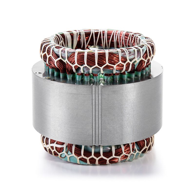
A motor or generator only works because of the continuous magnetic interaction between two components: the rotor and the stator. In an electric motor rotor stator system, the stator winding creates a rotating (or alternating) magnetic field, and the rotor core provides a low-reluctance path that lets this field pass through the rotor with minimal opposition. When the rotor's own magnetic field — generated by induced currents, permanent magnets, or DC-excited windings — tries to align with the stator's field, torque is produced.
If the rotor core were replaced by a non-magnetic material, the air-gap reluctance would increase dramatically, and the machine would require far more current to produce the same torque.
This is why rotor cores are always built from high-permeability magnetic steel rather than plastic, aluminum, or composite materials — permeability is what allows flux to concentrate rather than dissipate.
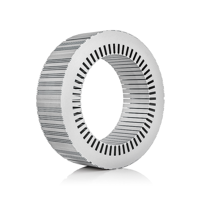
rotor core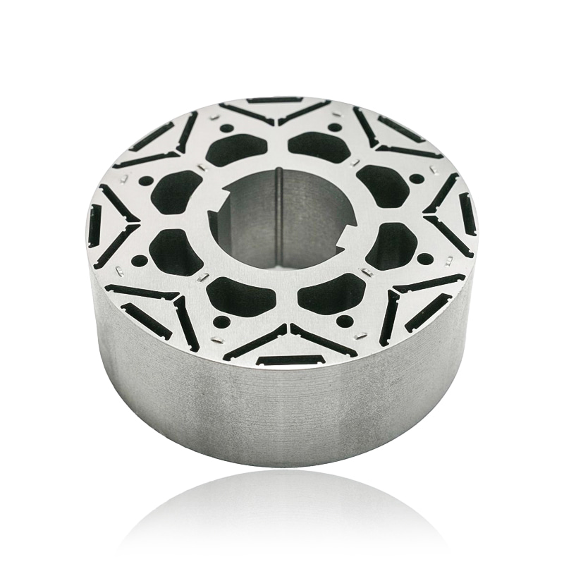
The tighter and more uniform the air gap between the rotor core and the stator bore, the more efficient this energy transfer becomes. Manufacturing tolerances in this gap — often held within 0.3 mm to 0.5 mm for industrial motors — directly affect how much of the input power converts into usable mechanical output.
Materials: Why Rotor Cores Use Silicon Steel Laminations
Rotor cores are almost never made from a single solid block of steel. Instead, they are built from thin, insulated sheets of electrical steel — typically silicon steel — stacked and pressed together. This lamination approach solves a specific problem: when a solid conductive core sits inside a changing magnetic field, it generates circulating eddy currents that heat the metal and waste energy.
Common Rotor Core Steel Grades
| Steel Grade | Silicon Content | Typical Use | Core Loss (W/kg @ 1.5T, 50Hz) |
|---|---|---|---|
| Non-oriented low-grade | 1.0% – 2.0% | Small fractional-HP motors | 4.5 – 6.0 |
| Non-oriented mid-grade | 2.0% – 3.0% | General industrial motors | 2.5 – 4.0 |
| High-efficiency non-oriented | 3.0% – 3.5% | Premium-efficiency and servo motors | 1.2 – 2.0 |
Higher silicon content increases electrical resistivity, which reduces eddy current losses, but it also makes the steel more brittle and harder to stamp. Manufacturers balance these two factors depending on whether the motor prioritizes cost, efficiency, or manufacturability.
Lamination Thickness and Its Effect on Losses
Eddy current losses increase with the square of lamination thickness, which is why thinner sheets are used in higher-frequency or higher-efficiency applications. A general relationship: cutting lamination thickness in half can reduce eddy current losses by roughly 75%, though hysteresis losses remain largely unaffected by thickness.
- 0.50 mm laminations — common in low-cost, low-speed motors
- 0.35 mm laminations — standard for most industrial induction motors
- 0.20 mm or thinner laminations — used in high-speed servo motors and high-frequency generators
Each lamination sheet is coated with a thin insulating layer, typically an inorganic or organic varnish, to prevent electrical continuity between layers. This insulation is what actually interrupts the eddy current loops — without it, a stack of laminations would behave electrically like a solid block.
Info
Lamination insulation coatings are typically only a few microns thick, yet they are what make the difference between an efficient rotor core and one that runs hot under load.
Torque Generation and Magnetic Flux Distribution
The rotor core's slot geometry determines how magnetic flux distributes across the rotor's circumference, which in turn affects torque smoothness, starting torque, and noise. Poorly designed slots create uneven flux density, leading to torque ripple, vibration, and audible whine.
Slot Design Considerations
Rotor slots are usually skewed relative to the shaft axis by one slot pitch across the core length. This skewing spreads out the interaction between rotor and stator slots over time, smoothing torque output and reducing cogging in both motoring and generating modes. In a well-designed electric motor rotor, this skew is measured and controlled to within fractions of a degree during stamping and stacking.
Common Rotor Core Types and Their Functional Differences
Not all rotor cores serve their function the same way. The construction method changes depending on the motor type and application.
- Squirrel-cage rotor core — aluminum or copper bars are cast or inserted directly into the laminated core slots and short-circuited by end rings, forming a self-contained conductor path with no external connections.
- Wound rotor core — insulated copper windings are inserted into the slots and connected to slip rings, allowing external resistance to be added for controlled starting torque.
- Permanent magnet rotor core — magnets are surface-mounted or embedded within the core, eliminating induced rotor current entirely and improving efficiency at the cost of higher material expense.
Each configuration still relies on the same underlying principle: the laminated steel core provides the low-reluctance magnetic path, while the conductors or magnets provide the source of the rotor's own magnetic field.
Thermal Behavior of the Rotor Core
Even with lamination and high-silicon steel, some core loss converts to heat. In continuously loaded industrial motors, rotor core temperature can rise 40°C to 70°C above ambient depending on cooling design, ventilation, and duty cycle. Because the rotor core sits closest to the source of induced current, it often runs hotter than the frame, making airflow across the rotor a critical design factor in enclosed motor housings.
Excessive heat accelerates insulation aging on rotor conductors and can gradually reduce the core's magnetic permeability, a phenomenon known as thermal aging of steel. This is one reason manufacturers specify maximum continuous operating temperatures and recommend derating motors used in poorly ventilated or high-ambient-temperature environments.
Warning
Sustained operation above a motor's rated temperature class does not just shorten winding life — it can permanently degrade the rotor core's magnetic performance over time.
Signs of Rotor Core Damage or Quality Issues
A degraded or poorly manufactured rotor core rarely causes total failure immediately. Instead, it produces gradual performance symptoms that experienced operators learn to recognize.
- Rising operating temperature under the same load conditions
- Increased current draw without a corresponding increase in output torque
- Audible humming, whining, or grinding not present when the motor was new
- Visible rust or lamination separation after exposure to moisture
- Vibration readings trending upward during routine condition monitoring
Corrosion between laminations is a particularly common failure mode in humid or outdoor environments. Once rust forms between sheets, the insulating varnish is compromised, eddy current losses climb, and localized hot spots can eventually damage adjacent windings or bearings.
Danger
Lamination corrosion is progressive and largely irreversible. Once insulation breakdown begins between sheets, replacement is almost always more reliable than repair.
How to Select the Right Rotor Core for an Application
Choosing a rotor core specification is not just about matching shaft diameter. Buyers and engineers should evaluate the full operating profile of the machine.
Key Selection Factors
- Operating speed range, since higher RPM applications benefit from thinner laminations to control eddy current losses
- Duty cycle and expected thermal load, which affects steel grade and cooling design
- Required starting torque, which influences whether a squirrel-cage or wound configuration is more suitable
- Environmental exposure, particularly humidity, which determines coating and corrosion protection needs
- Efficiency targets, since higher-silicon steel and thinner laminations reduce losses but add cost
For most general industrial applications, a mid-grade non-oriented silicon steel core with 0.35 mm laminations and standard skewed slots offers a practical balance of cost, efficiency, and durability. High-speed or precision applications, however, justify the added expense of thinner laminations and higher silicon content because the efficiency gains compound significantly over the motor's operating life.
Maintenance Considerations Specific to the Rotor Core
Unlike bearings or brushes, rotor cores are not typically serviceable components — once corrosion or lamination damage sets in, repair options are limited and often uneconomical compared to replacement. That said, several preventive practices extend rotor core life considerably.
- Keep the motor's ventilation paths clear to prevent heat buildup around the rotor assembly
- Avoid prolonged storage in humid environments without heaters or moisture barriers
- Monitor vibration and thermal trends to catch early-stage lamination or bar damage before it worsens
- Avoid repeated overloading, which accelerates insulation breakdown between laminations
Success
Motors with well-ventilated enclosures, moderate duty cycles, and dry storage conditions routinely see rotor cores outlast the rest of the machine's electrical components.
Closing Perspective
Ultimately, the rotor core's function is simple to state but demanding to engineer well: it must guide magnetic flux efficiently, support the rotor's conductors or magnets mechanically, and resist the thermal and electrical stresses of continuous operation. Every material choice, lamination thickness, and slot design decision made during manufacturing exists to serve that single purpose within the broader electric motor rotor stator system.
Previous article
How much efficiency is actually gained by using a laminated core versus a solid one?
next article
How does the carbon content of the base material influence the hysteresis loss in an Automotive Small Motor Stator Core?
Related News
-
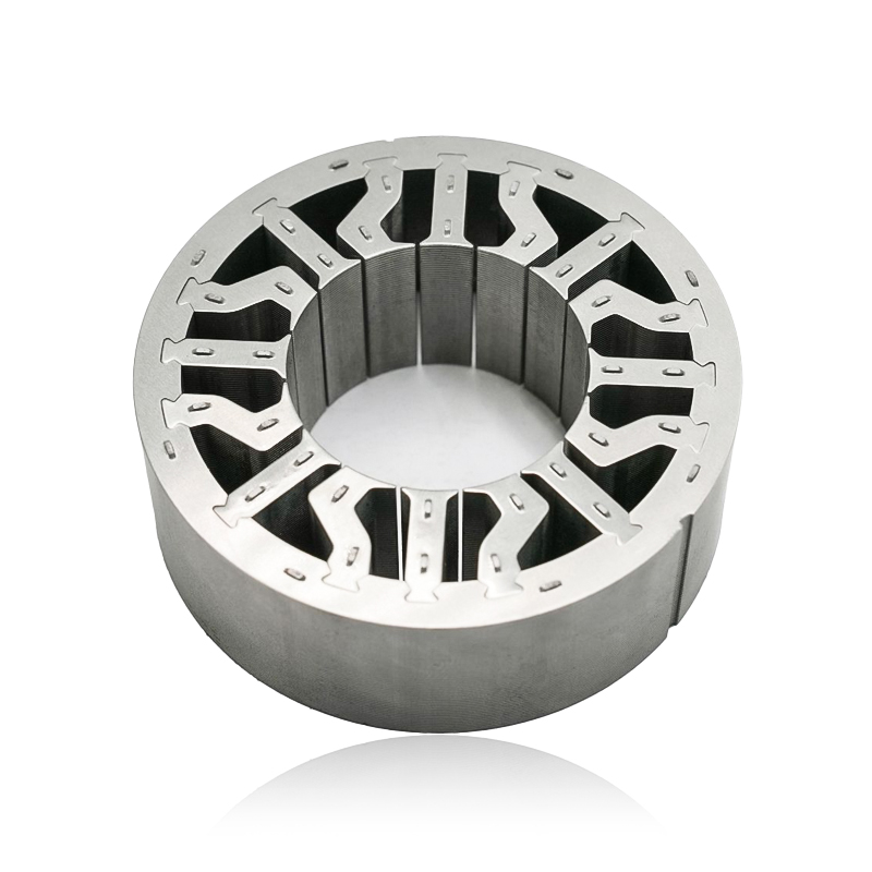
What are Stator and Rotor Cores? Stator Cores A stator core is the stationary component of an electric motor. It's the part that houses the copper windings, which, when an electric current passes thro...
See Details -
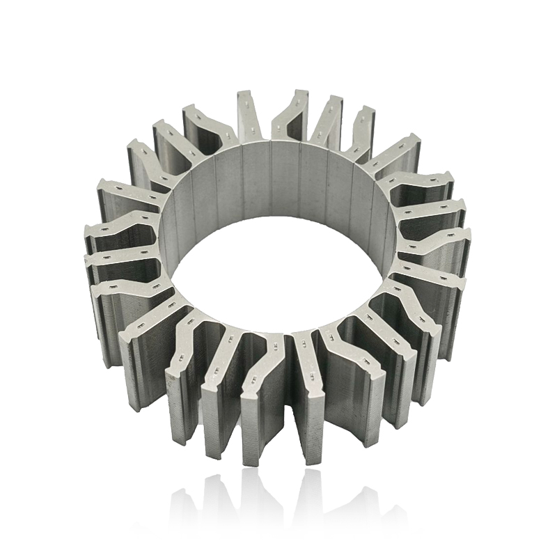
Introduction The modern automobile is a complex machine, and its evolution has been driven by continuous innovation in every component. While internal combustion engines have dominated the industry fo...
See Details -
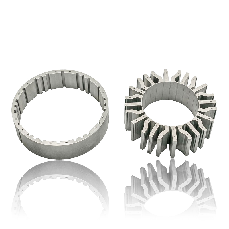
The Importance of Material Selection for Rotor and Stator Cores in Electric Vehicle Motors In the design of electric vehicle (EV) motors, material selection is a pivotal factor influencing the motor’s...
See Details -
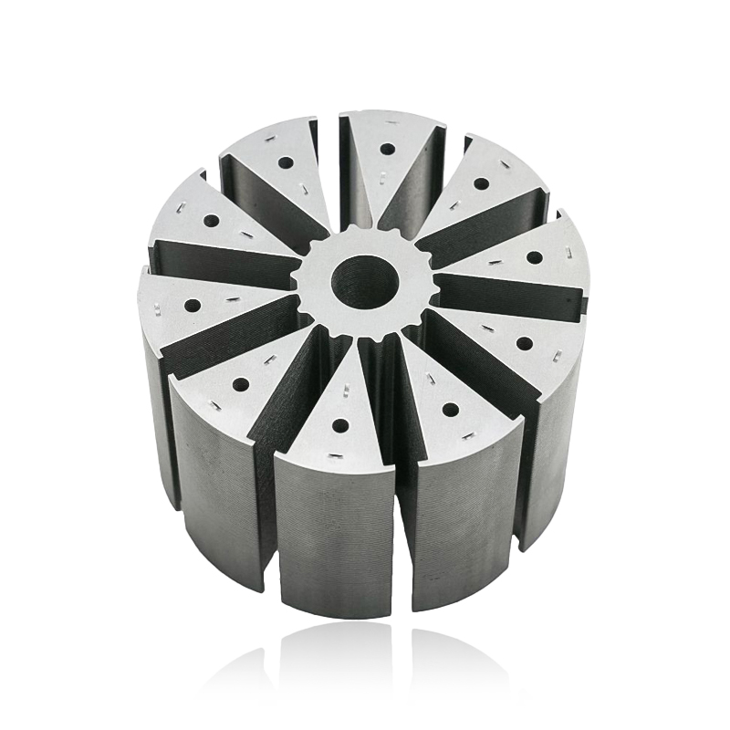
Introduction of automotive motor stator and rotor cores The increasing popularity of electric vehicles and hybrid electric vehicles has brought about significant advancements in automotive technology....
See Details


Zhejiang Jufeng Technology Co., Ltd. © All rights reserved
