
 简体中文
 English
 русский
 Español

Home / News / Industry News / Types of Motor Core Lamination: Steel, Thickness, Stacking and Coating
Types of Motor Core Lamination: Steel, Thickness, Stacking and Coating
Types of Motor Core Lamination: What Actually Changes Performance
Steel grade, sheet thickness, stacking method and coating are the four levers behind every lamination type. Each one trades efficiency against cost, stiffness, noise or scrap rate, and the trade is settled on the drawing rather than in the test cell.
A Lamination Type Is Four Decisions, Not One
Ask two stampers to quote the same stator drawing and you can receive two cores that measure identically at the outline and behave differently inside the machine. The reason is that a lamination type is not a single choice. It is four, and quotations rarely spell out all four in the same language.
The four variables that define the type:
- Steel grade — silicon content, alloy family, and whether the sheet is fully processed or semi-processed.
- Gauge — from 0.65 mm down to 0.10 mm, chosen against electrical frequency rather than against habit.
- Stacking method — interlock, weld, adhesive bond, rivet, or a loose stack held by clamping plates.
- Geometry — a single full-round punching, segmented arcs, or step-lapped layers with rotated seams.
Gauge and stacking method cause most of the surprises. Moving from 0.50 mm to 0.35 mm steel, or from interlocking to bonding, usually shifts iron loss across a wider band than swapping between two nominally similar grades of the same thickness.
Material Grades Behind the Main Lamination Types
The steel underneath a lamination sets its ceiling. Non-oriented silicon steel dominates rotating machines because its magnetic properties are broadly uniform in every direction of the sheet, which suits the rotating flux of a stator or rotor. Grain-oriented steel carries lower loss along the rolling direction but is direction-sensitive, so it belongs to transformers and only rarely to a rotating core.
Around those two families sits the menu most buyers actually choose from:
- Standard non-oriented silicon steel, 2.5–3.5% silicon — pumps, fans, appliances and general industrial drives, where cost per kilogram dominates the decision.
- High-silicon and silicon-aluminium grades — higher resistivity and lower eddy-current loss, paid for in brittleness and faster die wear.
- Nickel-iron alloys — very high permeability and low loss at low flux density; precision and instrument motors rather than traction.
- Cobalt-iron — the highest saturation flux density available in sheet form, reserved for machines where volume and mass are critical.
- Semi-processed versus fully processed sheet — semi-processed steel only reaches final magnetic properties after a decarburising anneal at the stamper, which rules it out for bonded or coated stacks that cannot survive that cycle.
| Material family | Typical gauge | Where it fits | Trade-off accepted |
|---|---|---|---|
| Standard non-oriented silicon steel | 0.50–0.65 mm | Pumps, fans, appliances, general industrial drives | Lowest cost per kilo, higher loss once frequency climbs |
| Thin-gauge non-oriented steel | 0.20–0.35 mm | EV traction, servo, high-speed spindles | Lower eddy loss, higher unit cost, faster punch wear |
| High-silicon or silicon-aluminium | 0.20–0.35 mm | Inverter-fed and high-frequency machines | Very low loss, brittle sheet, awkward to weld |
| Nickel-iron alloy | 0.05–0.35 mm | Precision, low-flux and instrument motors | Excellent permeability, high price, stress-sensitive |
| Cobalt-iron | 0.15–0.35 mm | Weight- and space-constrained machines | Highest saturation, highest cost, limited supply base |
Thickness: The Variable That Should Follow Frequency
Gauge is the variable most often copied from an older programme and least often re-checked. Classical eddy-current loss rises with the square of sheet thickness, so dropping from 0.50 mm to 0.35 mm removes roughly half of that component, and going to 0.27 mm removes about seventy percent of it. Hysteresis loss does not fall the same way, which is why the real gain is always smaller than the square-law figure suggests.
- Mains-fed machines at 50 or 60 Hz — 0.50 mm is the standard choice, and 0.65 mm still appears in small cost-driven motors.
- Inverter-fed industrial drives — 0.35 to 0.50 mm, depending on how much switching ripple the winding current carries.
- EV traction motors — 0.25 to 0.35 mm, occasionally 0.20 mm where the fundamental frequency is high.
- High-speed and high-frequency machines — 0.10 to 0.20 mm, usually adhesively bonded because thin sheet does not tolerate interlocking.
Thinner steel is not automatically the better lamination. Coating takes a larger share of the stack as gauge falls, so stacking factor slips from roughly 0.96 at 0.50 mm to about 0.90–0.93 at 0.20 mm, and part of the loss saving is paid back in a longer core. Thin sheet also burrs faster, handles worse on the press line, and multiplies the number of pieces in every stack.
Stacking Methods: Where Lamination Types Really Diverge
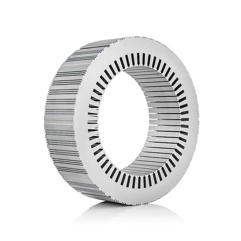
Identical steel, identical gauge, different joint, and a measurable difference in loss, stiffness and noise. Every mechanical connection between laminations creates a small electrical path across the insulation, and that path is precisely what the lamination exists to prevent.
| Method | Effect on insulation | Mechanical behaviour | Cost position | Typical use |
|---|---|---|---|---|
| Interlock: V-notch, dimple, dovetail | Local short circuit at each joint | Good in-plane stiffness, moderate in torsion | Lowest | High-volume appliance, pump and fan cores |
| Laser or TIG weld | Short circuit concentrated along the seam | High, suitable for rotor stacks | Low to medium | Industrial drives, medium and large stators |
| Adhesive bond via self-bonding coating | Effectively none across the stack | High, with useful damping | Medium to high | EV traction, servo, low-noise machines |
| Rivet, through-bolt or key | Concentrated at the fastener | Very high, tolerant of large diameters | Medium | Wind, rail and large generator cores |
| Loose stack with clamping plates | None until the housing clamps it | Set by the frame rather than the stack | Medium | Prototypes and low-volume builds |
Welding is the most common compromise: fast, cheap and strong, but the weld bead saturates locally and bridges the coating between sheets. Keeping weld count and bead length under control is a design decision with a loss target attached, not a shop-floor preference. Bonding goes the other way, preserving interlaminar resistance and adding damping that shows up as lower structure-borne noise, in exchange for a curing press, a controlled temperature profile and more handling discipline.
Every interlock dimple, weld bead and rivet is a small short circuit between sheets. The question is never whether the joint costs loss, but whether the stiffness it buys is worth the loss it costs.
Full-Round, Segmented and Rotated Stacks
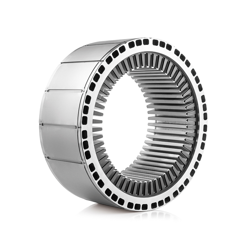
Diameter decides this one. A full-round punching keeps concentricity tight and the stack simple, but the material punched out of the centre becomes scrap, and die cost climbs steeply beyond roughly 400 to 500 mm outside diameter. Above that, segmented laminations are punched as arcs or pie slices on smaller, cheaper dies and assembled into a ring, which recovers material and lets one die serve several frame sizes.
Segmentation has its own cost: every segment joint interrupts the flux path. Step-lapping and rotating successive layers so that seams never line up through the stack spreads the reluctance around the ring and keeps the penalty small. A four-segment core rotated by 90 degrees per layer behaves noticeably better than the same segments stacked with aligned seams.
The same principle explains rotor skew. Skewing the stack by about one slot pitch trades a little torque for lower cogging and quieter running, and it is a lamination-level decision rather than an assembly one, because it changes the tooling.
Coatings Belong in the Specification Too
Coating is often treated as a purchasing detail, yet it is a design parameter. The insulating layer sets interlaminar resistance, occupies stack height, and decides whether a core can be welded, annealed or bonded without losing the properties the steel was bought for.
Thin organic coatings are the default for weldable cores that need a high stacking factor. Thicker inorganic or ceramic-filled coatings raise interlaminar resistance and survive stress-relief annealing, paid for in stacking factor and punchability. Self-bonding coatings act as the adhesive in a bonded stack, which turns the cure cycle into a process control point rather than a material datasheet, and under-curing surfaces much later as delamination.
Matching the Type to the Application
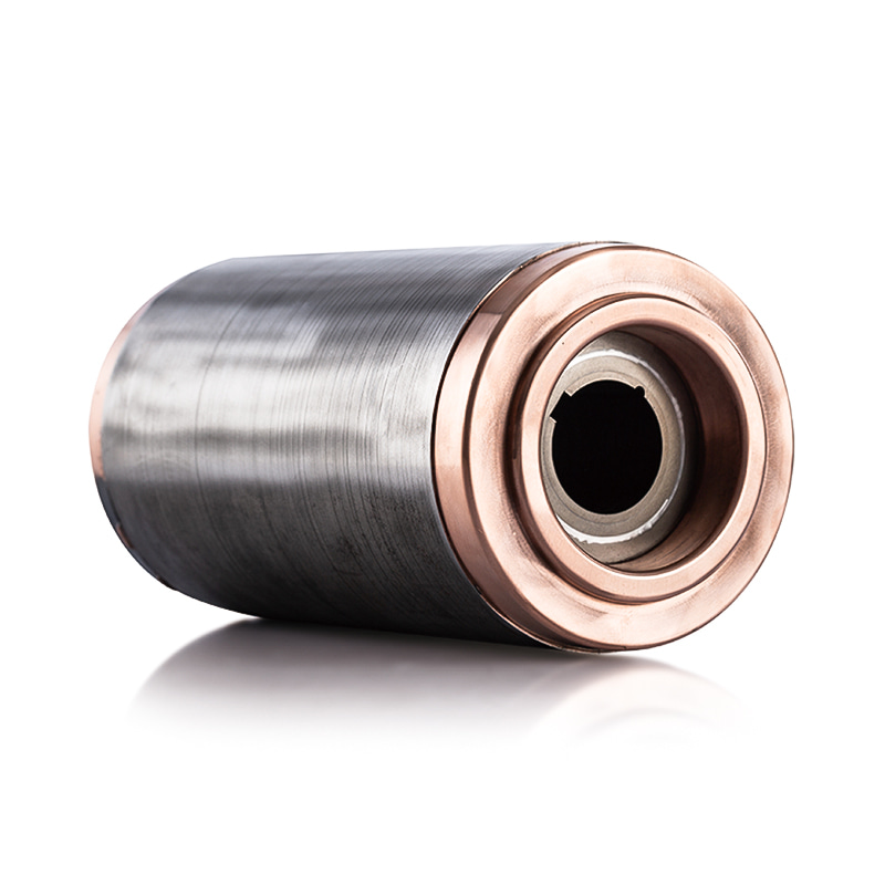
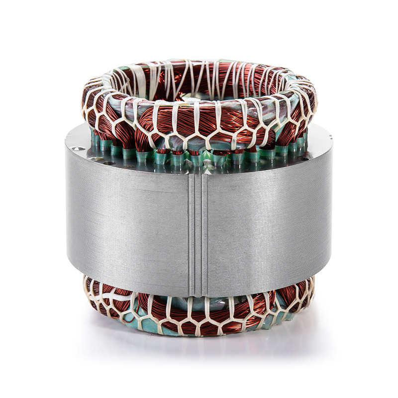
Read across the market and lamination types sort themselves by duty rather than by size. The full motor stator and rotor core range is organised along exactly these lines, which makes the comparison easier than arguing grade by grade.
Electric vehicle drive motors run thin gauges, bonded or segmented-and-rotated stacks, and tight burr limits, because the loss budget is counted in single-digit watts and the acoustic target in decibels. Here the lamination type is chosen to survive high fundamental frequency, PWM ripple and thermal cycling at the same time.
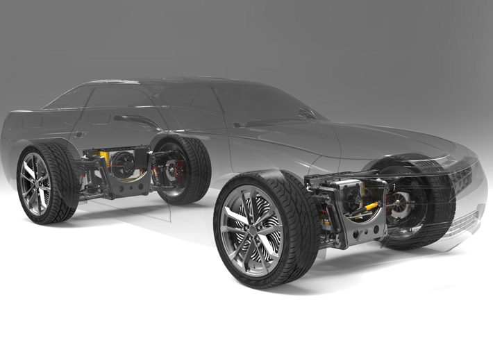 Electric Vehicle Drive Motor Stator and Rotor CoreEV drive motor stator and rotor core set for thin-gauge, bonded or segmented stacks, aimed at high-frequency, PWM and thermal-cycling demands.View Product →
Wind power generator cores move in the opposite direction: large diameters, segmented arcs, thicker gauge and bolted or welded joints, where fatigue resistance and concentricity matter more than a fraction of a percent of efficiency.
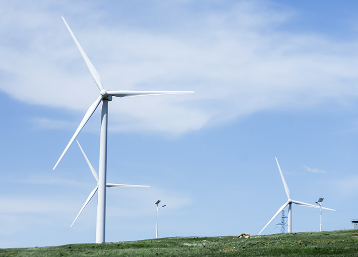 Wind Power Generator Motor Stator and Rotor CoresWind turbine generator stator and rotor cores in large-diameter, segmented designs where fatigue resistance and concentricity matter more than small efficiency gains.View Product →
Servo motor cores sit between the two, with thin sheet, high pole counts and a slot geometry that has to keep cogging low while the rotor accelerates and reverses thousands of times a shift.
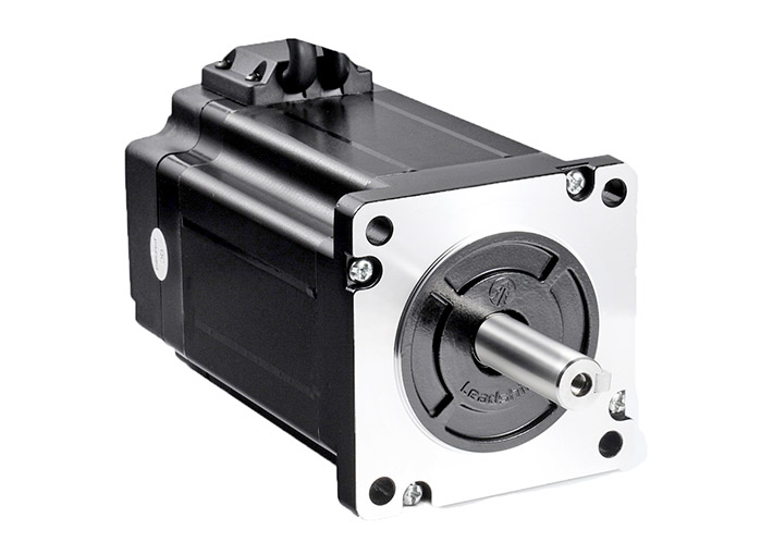 Servo Motor Stator and Rotor CorePrecision laminated servo stator and rotor cores for thin-sheet, high-pole-count designs that keep cogging low under repeated acceleration and reversal.View Product →
Appliance, pump and fan cores remain the cost-led case: 0.50 mm non-oriented steel, interlocked, high volume, minimal secondary operations. Specifying anything finer there is money spent without a matching return.
A Practical Sequence for Choosing Between Types
- Fix the electrical operating point first: fundamental frequency, expected PWM ripple, peak flux density and the loss budget the thermal design can absorb.
- Select gauge against that budget rather than against the previous programme, and confirm the stacking-factor penalty does not eat the gain.
- Choose the joint from mechanical duty: rotor surface speed, vibration spectrum, axial clamping and whether the core must be restacked after a fault.
- Choose geometry from diameter and die budget: full-round below roughly 400 to 500 mm, segmented above it, step-lapped where segments are used.
- Choose the coating for the process route the part will actually follow, whether that is welding, annealing, bonding or none of them.
- Confirm the supplier can hold the choice: press tonnage, die condition, burr control, bonding line and measurement capability.
What to Inspect Before Approving a Sample
Most lamination-type failures are visible at sample approval and invisible afterwards. Burr height above the drawing limit shorts adjacent sheets and stacks unevenly; an interlaminar resistance reading below specification on a bonded core usually means under-cured adhesive; a stacking factor under the quoted value points to excess coating or poor flatness.
- Burr height — measured, not judged by feel, and checked at the slot edges as well as the outside diameter.
- Interlaminar resistance — on bonded and coated stacks, with the cure record that produced the sample.
- Core loss on a production lot — not on a hand-built sample from selected steel.
- Dimensional capability — bore roundness, slot position and squareness through the stack, not just first-piece dimensions.
- Joint consistency — weld count and position, interlock pattern, adhesive coverage, all of which drift quietly during ramp-up.
A well-specified core behaves boringly: loss lands inside the budget, noise sits at the predicted level, and the second and third production lots match the first. That consistency is the real output of choosing the right lamination type at the drawing stage.
The short version is that types of motor core lamination are separated less by what they are called and more by four measurable choices: grade, gauge, joint and geometry, with coating binding them together. Get those four aligned with the operating frequency and the mechanical duty, and the rest of the specification follows. Get them copied from an older drawing, and the mismatch shows up as heat, noise or scrap nobody can trace back to a single line on the print.
If you have a drawing, an operating point and a loss target, send them across through the contact page and the lamination type can be narrowed down against real tooling and process capability rather than against a catalogue description.
Previous article
No more
next article
How to Make a Stator Core: Steel Selection, Punching, Stacking and Inspection
Related News
-
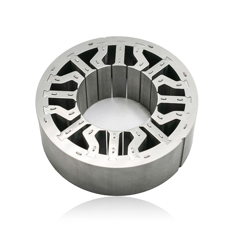
What are Stator and Rotor Cores? Stator Cores A stator core is the stationary component of an electric motor. It's the part that houses the copper windings, which, when an electric current passes thro...
See Details -
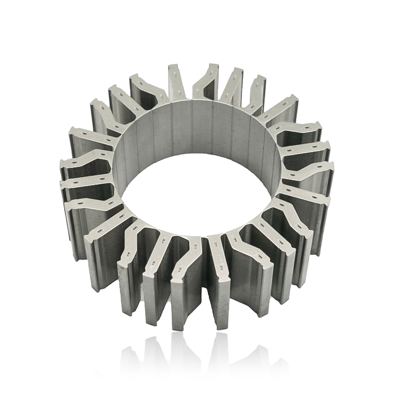
Introduction The modern automobile is a complex machine, and its evolution has been driven by continuous innovation in every component. While internal combustion engines have dominated the industry fo...
See Details -
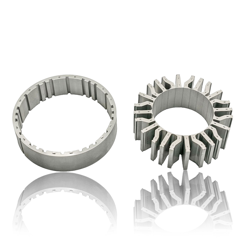
The Importance of Material Selection for Rotor and Stator Cores in Electric Vehicle Motors In the design of electric vehicle (EV) motors, material selection is a pivotal factor influencing the motor’s...
See Details -
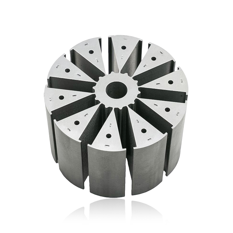
Introduction of automotive motor stator and rotor cores The increasing popularity of electric vehicles and hybrid electric vehicles has brought about significant advancements in automotive technology....
See Details


Zhejiang Jufeng Technology Co., Ltd. © All rights reserved
