
 简体中文
 English
 русский
 Español

Home / News / Industry News / The Slinky Lamination Stator Core: Process, Benefits, and Supplier Guide
The Slinky Lamination Stator Core: Process, Benefits, and Supplier Guide
Slinky Lamination Stator Core: The Quiet Efficiency Engine of Small Motors
One continuous strip of electrical steel, wound into a finished stator core. No loose punchings, no skeleton scrap, and a magnetic path that repeats itself turn after turn.
Every small-motor program reaches the same crossroads: the buyer wants a core that matches the slot profile, the designer wants stable magnetics from the first unit to the millionth, and the cost team wants a stamping yield that works at high volume. That is where the slinky lamination stator core enters the discussion.
The short version is direct: a slinky lamination stator core is manufactured from one continuous strip of silicon steel, stamped tooth by tooth in a progressive die, then wound into a cylindrical stack. No individual lamination rings need handling, sorting, or alignment. That one difference explains the material utilisation, tooling economy, and dimensional consistency the process is known for.
What Is a Slinky Lamination Stator Core?
Start with the part itself. In a slinky lamination stator core, the laminations do not exist as separate rings. The core is one spiral: a long strip of electrical steel, stamped with teeth and slots, then coiled around a mandrel until the stack reaches the required height. The finished part looks like a coiled spring — hence the name.
Each turn of the strip is only part of the circle; the next tooth continues the slot pattern as the coil builds. Layers are secured with interlocking notches, resistance welding, or structural adhesive. On the electrical side, the grain of the steel follows the strip direction, so the flux path is oriented consistently in every turn — something random stacking of round punchings cannot guarantee.
The Manufacturing Sequence: From Steel Strip to Finished Core
A slinky line looks like a standard high-speed press line until the die opens. The strip is paid off a coil and indexed through a progressive die; each press stroke performs a different operation — pilot-hole piercing, tooth notching, slot cutting, contour trimming, and coining. Every stroke advances the strip by exactly one tooth pitch, so the slot count of the finished core is fixed by the die, not by the winding process.
The profiled strip then enters a winding unit and is pulled around the mandrel under controlled tension. That tension decides how tightly the layers close and whether the core stays cylindrical. Once the target stack height is reached, the strip is cut, the ends are joined, and both faces are squared. A light flattening or burnishing step usually follows to hold stack height within roughly ±0.1 to 0.2 mm.
The closure weld deserves special attention. If it burns through more than one or two layers, interlamination shorts raise core loss immediately and can show up later as a hot spot on the dynamometer.
Press speeds range from about 120 to 400 strokes per minute depending on strip width, tooth count, and material thickness. At the top of that range, one press produces a finished core every few seconds — the reason the process stays competitive for programmes running in the millions. The full route, including the stamping and quality-control disciplines behind it, is detailed in our overview of how stator core laminations are manufactured.
Why the Slinky Process Wins on Cost
The process was invented to eliminate waste. Conventional blanking punches each ring from a wider strip, and the skeleton between rings becomes scrap. In the slinky route the strip itself becomes the core, so scrap is limited to pilot holes, slot openings, and trim edges. Material utilisation typically reaches 90 to 98 percent, against roughly 60 to 75 percent for small-stator blanking.
That difference reshapes project economics in five ways:
- Material utilisation. Every extra point of yield appears directly in the unit price.
- Tooling investment. The slinky tool replaces the blanking die and its skeleton handling.
- Stack height flexibility. Stack length becomes a winding parameter, not a tooling change.
- Magnetic consistency. The flux path follows the rolling direction in every turn.
- Less manual handling. No loose laminations to stack, rotate, or align.
A quick way to estimate the effect: a stator that blanks at roughly 68 percent yield today can recover close to a third of the steel cost with a slinky layout, before labour or tooling benefits are counted.
The steel you buy becomes the magnetic path you sell. A slinky core cuts away almost nothing between the incoming coil and the finished stack.
Large-diameter cores become difficult to wind tightly, and very wide or deep slots tax the winding unit. In practice, the process is most competitive in the 20 to 120 mm range.
Slinky vs Conventional Stacked Cores
Neither process is universally better; each favours a different set of constraints. The table below shows the points that usually decide the selection.
| Factor | Slinky continuous strip | Conventional stacked laminations |
|---|---|---|
| Material utilisation | 90–98% | 60–75% |
| Tooling investment | Lower; no separate blanking die | Higher with compound blanking |
| Stack height change | Adjust winding turns | Adjust stacking height in assembly |
| Grain orientation | Uniform along the strip | Depends on stamping layout |
| Typical core OD range | Roughly 20–120 mm | 40 mm upwards, including segmented |
| Joining approach | Interlock, weld, or bond at strip ends | Interlock, weld, or bond across the stack |
The pattern is clear. When volume is high, the core is small enough to wind reliably, and tooling cost matters, the slinky route usually delivers the lowest total cost. For large, deeply slotted, or low-volume cores, conventional stacked laminations remain the pragmatic choice.
Applications Where Slinky Stator Cores Are the Natural Choice
High material yield and robust tooling make slinky cores standard where the bore is small and the slot shape is stable across long runs: washing machines, compressor motors, circulator pumps, power tools, small industrial drives, and auxiliary vehicle motors.
Home appliances are the classic fit — drum-drive and compressor motors run at high annual volumes with geometry that stays stable for years. Our product range keeps a dedicated category for these designs.
 Home Appliance Motor Stator and Rotor CoresExplore laminated stator and rotor cores designed for washing machines, refrigerators, and fans, emphasizing efficiency and reduced electrical losses.View Product →
Water pumps sit close behind. Gland pumps and circulators need a quiet, efficient magnetic path in a compact envelope, and the winding process delivers the dense tooth structure they prefer.
 Water Pump Motor Stator and Rotor CoreA compact, efficient magnetic path for gland pumps and circulators, with engineered laminations to minimize energy losses in both domestic and industrial systems.View Product →
Power tools add a different constraint: sustained loading and vibration make stack tightness and joining quality decisive, which is why electric-tool motors form their own product category.
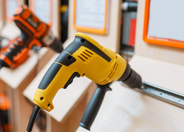 Electric Tool Motor Stator and Rotor CoreHigh-speed BLDC cores for cordless power tools, built with thin silicon steel and robust joining to withstand vibration and sustained loading.View Product →
These recipes are not interchangeable. The material, coating, and stacking method that work for a pump stator do not automatically transfer to a drill motor.
Materials, Tolerances, and the Details That Matter
Electrical steel grade and thickness set the efficiency ceiling. Slinky cores commonly use 0.35 mm or 0.50 mm material, such as 35A300 or 50A470 in JIS terms, or M19 to M47 in the AISI convention. Thinner material cuts eddy-current loss at high speed; thicker material lowers cost and adds rigidity during winding.
The insulation coating is just as important. The strip is sheared and coined repeatedly in the die; the coating must survive that mechanical abuse and still separate the layers after winding. C4 and C5 coatings cover most slinky applications, but the exact class should be confirmed before tooling is cut.
Watch winding tension closely. Too little tension opens the layers after joining; too much tension distorts the profile near the mandrel. A supplier that cannot document tension settings and stack-height measurements on the production floor is gambling with your motor efficiency.
Tolerance sheets look different from stacked-core drawings. Slot pitch, bore roundness, stack-height parallelism, and burr height are critical because they originate in the die and winding unit rather than in a stacking fixture.
What to Verify Before Choosing a Supplier
A slinky line looks impressive on a factory tour; the discipline shows up in documentation. Checks that matter when evaluating a supplier:
- Material provenance — steel grade, thickness, and coating class, traceable to the coil certificate for every batch.
- First-article reports — slot pitch, bore, stack height, out-of-square, and burr data compared against a realistic Cpk target.
- In-process records — strip tension, joining current or temperature, and final stack compression.
- Design and development support — slot geometry and stacking issues resolved before the die is cut, not after the first rejected batch.
- Measurement and testing routines that mirror your drawing tolerances, from height gauges to core-loss testing.
A well-run slinky programme shows up in stable capability indices, not in a clean showroom. Ask for capability data on a comparable core, then watch the line during a real production run.
The strongest supplier combines stamping capability with application knowledge: material recommendations, die design, prototyping, measurement, and volume release under one roof. At Jufeng Technology we build motor stator and rotor cores across appliance, pump, and tool categories, following the same sequence for every new programme. If you are comparing processes for an upcoming motor, it is worth discussing your slot geometry and volumes with the team that will build the tool.
A slinky lamination stator core is rarely the first thing sketched on the whiteboard, yet it is one of the most efficient answers when the motor is small, the volume is high, and unit price decides the programme.
Evaluate the core size, confirm the slot geometry with a capable stamper, and ask for measurements that prove the process is under control. Those three steps will tell you whether the slinky route belongs in your next motor.
Previous article
Motor Lamination Bonding: What a Quality Bond Means for Stator and Rotor Cores
next article
Motor core lamination process: Applications, Selection Criteria, and Practical Guidance
Related News
-
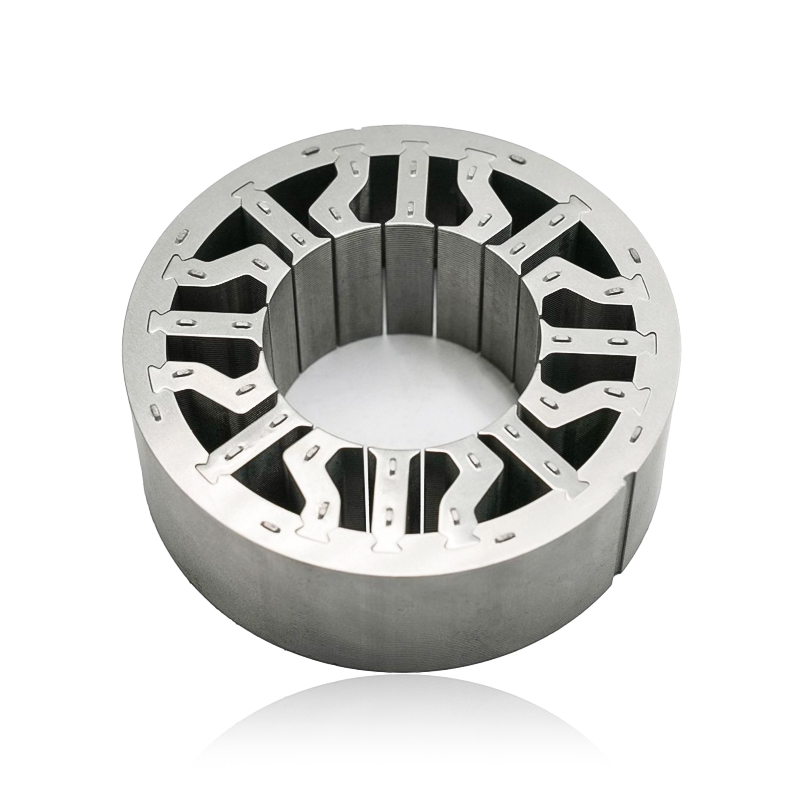
What are Stator and Rotor Cores? Stator Cores A stator core is the stationary component of an electric motor. It's the part that houses the copper windings, which, when an electric current passes thro...
See Details -
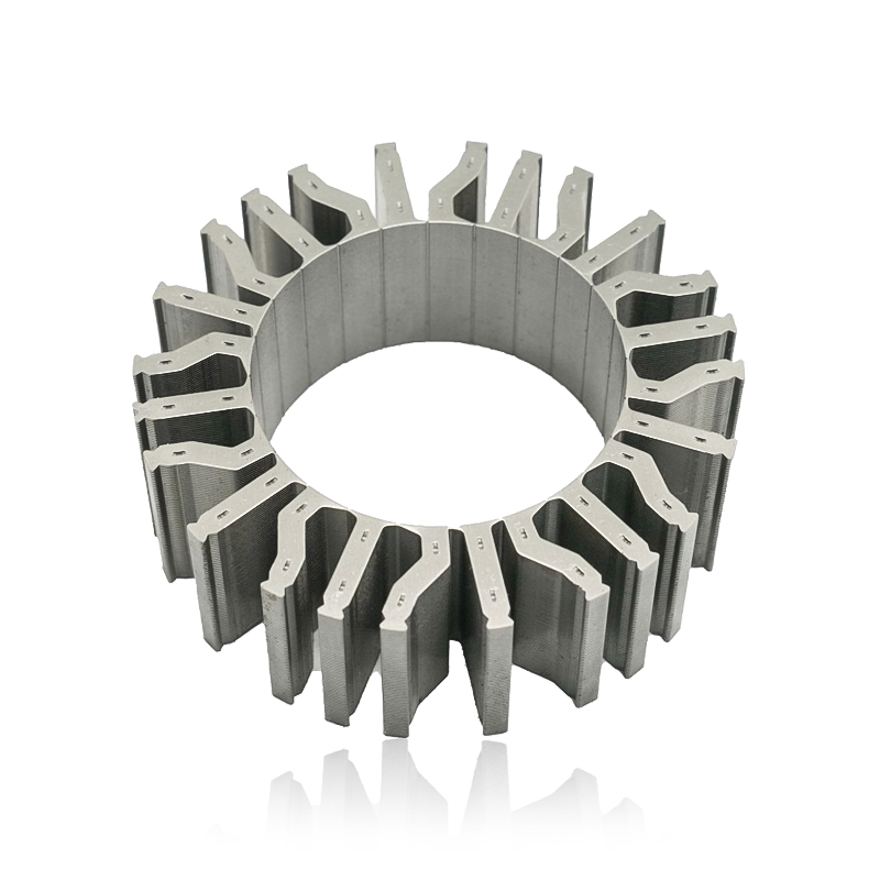
Introduction The modern automobile is a complex machine, and its evolution has been driven by continuous innovation in every component. While internal combustion engines have dominated the industry fo...
See Details -
The Importance of Material Selection for Rotor and Stator Cores in Electric Vehicle Motors In the design of electric vehicle (EV) motors, material selection is a pivotal factor influencing the motor’s...
See Details -
Introduction of automotive motor stator and rotor cores The increasing popularity of electric vehicles and hybrid electric vehicles has brought about significant advancements in automotive technology....
See Details


Zhejiang Jufeng Technology Co., Ltd. © All rights reserved
