
 简体中文
 English
 русский
 Español

Home / News / Industry News / How to Make a Stator Core: Steel Selection, Punching, Stacking and Inspection
How to Make a Stator Core: Steel Selection, Punching, Stacking and Inspection
How to Make a Stator Core That Holds Its Performance
The short answer is straightforward: a stator core is made by punching thin electrical steel laminations, stacking them under controlled pressure, joining the stack, and verifying the magnetic and dimensional result. The useful answer is less straightforward. Core loss, noise, and service life are shaped by choices made before the first coil is wound: steel grade, lamination thickness, die clearance, burr height, interlock pattern, annealing cycle, and coating integrity.
That is why a core can pass a dimensional layout and still run hot, buzz, or fail endurance testing. A supplier who quotes only the drawing is quoting half the part. The purchasing decision should follow the process from steel coil to finished stack.
Choose Electrical Steel Before You Choose the Press
Most stator cores use non-oriented silicon steel. Thickness commonly sits between 0.20 mm and 0.65 mm, with 0.35 mm and 0.50 mm appearing often in industrial and automotive work. Thinner gauge can reduce eddy-current loss, but it increases lamination count, handling cost, and die wear. Higher silicon content raises resistivity and lowers loss, while it can reduce punchability and saturation flux density.
The practical starting point is the motor duty point: electrical frequency, flux density, allowable temperature rise, and available stack length. A high-speed traction motor, a ceiling fan motor, and a wind generator do not share the same material compromise.
- Core loss at the actual operating frequency, not only at 50 or 60 Hz
- Yield strength and punchability for die life
- Insulation coating class for annealing and varnish compatibility
- Thickness tolerance and flatness for stacking factor
For EV drive motors, material and cooling strategy should be fixed together. A low-loss grade that cannot survive the press, stacking, or thermal cycle is not a cost saving.
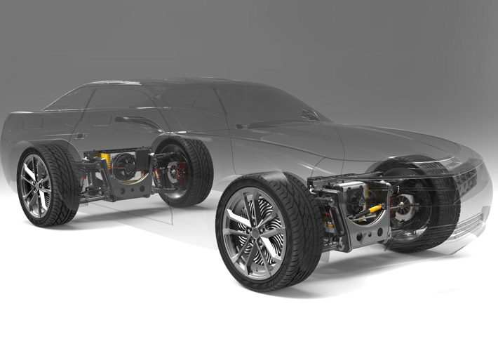 EV Drive Motor Stator and Rotor CoreStator and rotor cores for electric propulsion, with stamped electrical-steel laminations, precision air-gap control, and cooling details relevant to EV drive-motor material and process decisions.View Product →
Punching Sets the Hidden Tolerances
Punching is not just cutting. Die clearance determines the shear zone, fracture zone, and burr. A burr that feels minor can short adjacent laminations, raise eddy-current loss, and create local hot spots. In higher-volume work, carbide dies and progressive tooling are common, but maintenance discipline matters more than the tool label. Frequent burr checks, die sharpening records, and strip cleanliness protect the process.
For large or segmented stators, the lamination may be split to improve material yield or winding access. Segmentation introduces joint interfaces; those interfaces must be controlled for fit, magnetic continuity, and stack alignment. A segmented pattern that looks efficient on the material sheet can lose its advantage in assembly. The wider stator core lamination process follows the same rule: every added operation must earn its place in the final magnetic result.
Burr height is one of the cheapest things to inspect and one of the most expensive things to ignore.
Stack, Join, and Release Stress
Laminations are stacked to the required stack length and joined by interlock, welding, bonding, or a combination. Interlock is fast and clean but creates local magnetic shorting and can affect flatness. Welding is robust but puts heat and conductive bridges along the outer edge. Bonding gives good damping and insulation but needs curing control and surface preparation. The right choice depends on application frequency, vibration, and rework tolerance.
| Joining method | Best fit | Main watchout |
|---|---|---|
| Interlock | High-volume appliance and small motor cores | Local shorting, stack flatness, and tool wear at the interlock feature |
| Welding | Industrial and traction cores needing a stiff stack | Heat-affected zones and conductive bridges along the weld |
| Bonding | Low-noise or high-frequency cores needing damping | Adhesive coverage, curing control, and dimensional growth |
For high-volume appliance motors, interlock consistency and stack flatness often matter more than a narrow magnetic optimization. For a low-noise drive, bonding may justify its process cost.
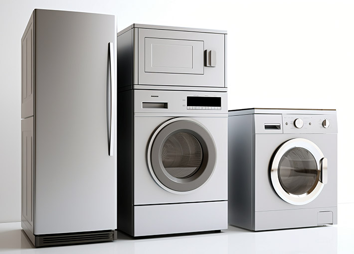 Home Appliance Motor Stator and Rotor CoresLaminated stator and rotor cores for washing machines, refrigerators, and fans, covering silicon-steel choice, stamping, self-lamination, and annealing considerations for appliance-motor production.View Product →
After joining, stress-relief annealing can recover permeability and lower core loss after punching and stacking. The cycle must match the steel coating. Too high a temperature or a wrong atmosphere can damage interlamination insulation. If the steel carries a specific annealing coating, the core maker and heat treater should agree on the cycle before production.
Inspection Should Mirror Motor Behavior
Final inspection should not stop at outside diameter and slot width. A useful release plan includes burr height, lamination thickness, stack length, squareness, interlamination resistance, core loss, and a magnetic signature check when the motor is sensitive to torque ripple. For rotors, balance and lamination security deserve their own checks.
- Dimensional checks: slot profile, bore, keyway, and stack length
- Magnetic checks: core loss, permeability sample, and interlamination resistance
- Mechanical checks: flatness, twist, weld or bond strength, and balance where applicable
- Traceability checks: steel heat number, die history, and annealing batch
A sample that passes at low speed can still fail at the drive frequency. Test conditions should match the intended motor's electrical and thermal reality as closely as the supplier's laboratory allows. Ask for the measurement method, not only the result.
Wind power generator cores add another layer: large-diameter flatness, corrosion protection, and service access. A stack that is acceptable on a bench can be difficult to protect and assemble in the field.
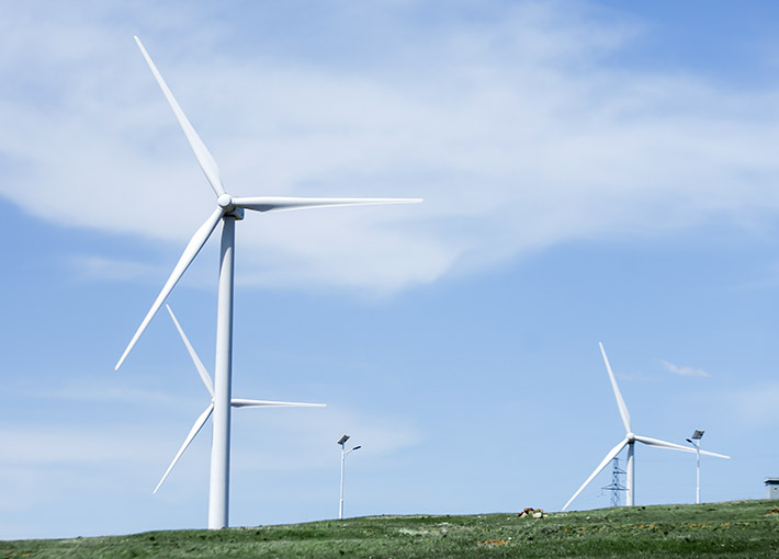 Wind Turbine Generator Stator and Rotor CoresLaminated stator and rotor cores for wind turbine generators, covering electrical-steel selection, rotor construction, and assembly methods relevant to large-diameter flatness and coating durability.View Product →
Match the Core to the Application
Application sets the hierarchy of risks. An EV traction motor cares about high-frequency loss, cooling, and stack stiffness. A home appliance motor cares about cost, repeatability, and low noise. A wind generator cares about flatness, coating durability, and long service access. A servo motor cares about slot geometry and low cogging. A pump motor cares about bore tolerance and winding fit.
Do not let a generic core drawing travel across applications. The same outside diameter can hide different slot geometry, yoke thickness, material grade, and joining method. A core optimized for one duty point may be oversized, noisy, or thermally poor in another. That is why a serious core offer is usually organized by application rather than by a single catalog size.
Supplier Questions That Reduce Risk
When comparing quotes, ask how the supplier will hold the magnetic result, not only the drawing. Request the steel certificate, die maintenance record, burr limit, stacking and joining specification, annealing route, inspection plan, and change notification process. A capable supplier will show where the process is controlled and where it is measured.
- Which steel grade and thickness are proposed, and why for this duty point?
- What burr height and coating integrity limits will be inspected?
- How is stack length controlled across the production run?
- Which joining method is used, and what magnetic effect has been validated?
- What happens to the process when the material lot changes?
For a production program, ask for samples from more than one lot and more than one die cavity when applicable. A single polished sample proves the drawing can exist. It does not prove the process can repeat.
If you are ready to discuss your stator core project, bring the duty point, stack drawing, annual volume, and quality standard to the first conversation. The earlier those facts are on the table, the fewer surprises appear at PPAP or ramp-up.
The stator core is a magnetic assembly made by a mechanical process. Treat it that way: select the steel for the duty point, control the punch and stack, validate the joining and annealing system, and inspect what the motor will actually feel. That approach will not make a core inexpensive by default, but it will make the cost predictable.
Previous article
Types of Motor Core Lamination: Steel, Thickness, Stacking and Coating
next article
Motor Lamination Bonding: What a Quality Bond Means for Stator and Rotor Cores
Related News
-
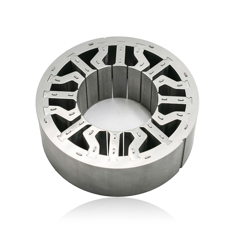
What are Stator and Rotor Cores? Stator Cores A stator core is the stationary component of an electric motor. It's the part that houses the copper windings, which, when an electric current passes thro...
See Details -
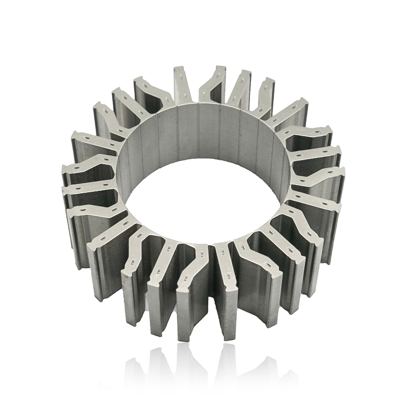
Introduction The modern automobile is a complex machine, and its evolution has been driven by continuous innovation in every component. While internal combustion engines have dominated the industry fo...
See Details -
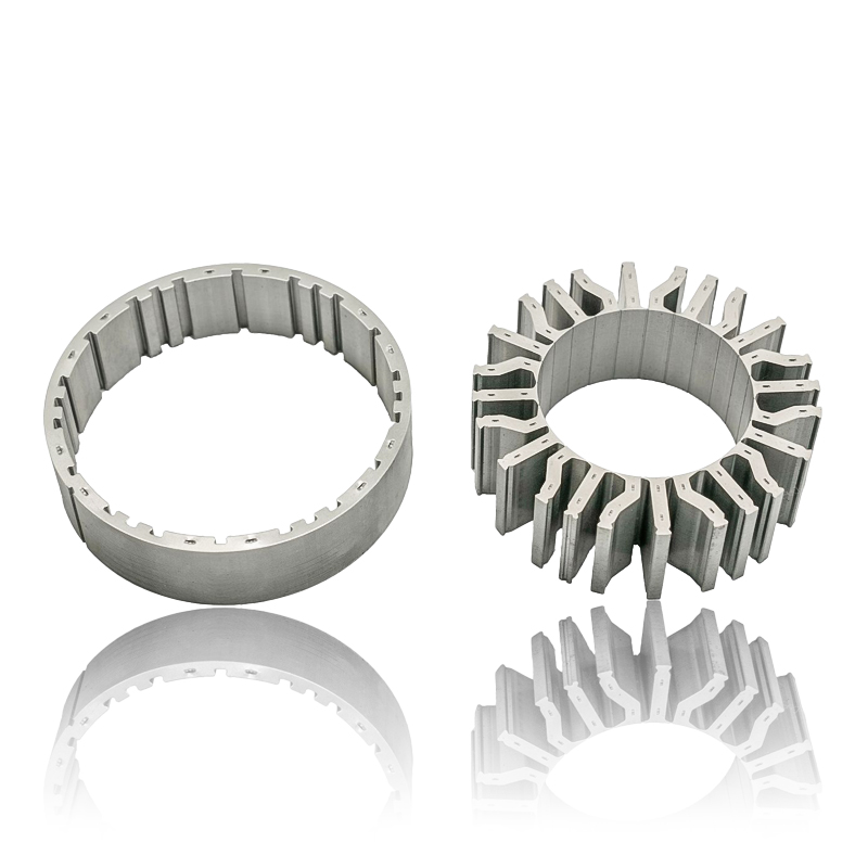
The Importance of Material Selection for Rotor and Stator Cores in Electric Vehicle Motors In the design of electric vehicle (EV) motors, material selection is a pivotal factor influencing the motor’s...
See Details -
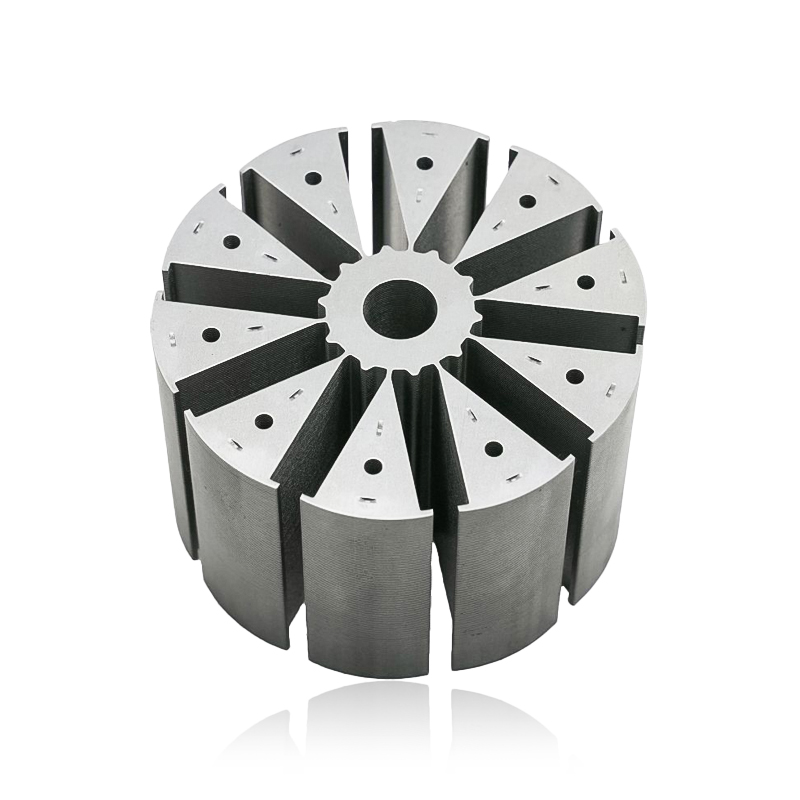
Introduction of automotive motor stator and rotor cores The increasing popularity of electric vehicles and hybrid electric vehicles has brought about significant advancements in automotive technology....
See Details


Zhejiang Jufeng Technology Co., Ltd. © All rights reserved
