
 简体中文
简体中文 English
 русский
 Español
Home / News / Industry News / How Stator Core Laminations Are Manufactured: Process, Materials & Quality Control
How Stator Core Laminations Are Manufactured: Process, Materials & Quality Control
Motor failures often show up as excessive heat, vibration, or efficiency loss. In many cases, the root cause can be traced back to the stator core and the way its laminations were manufactured. The manufacturing process of stator core laminations determines the magnetic performance, mechanical integrity, and long-term reliability of the motor that surrounds them.
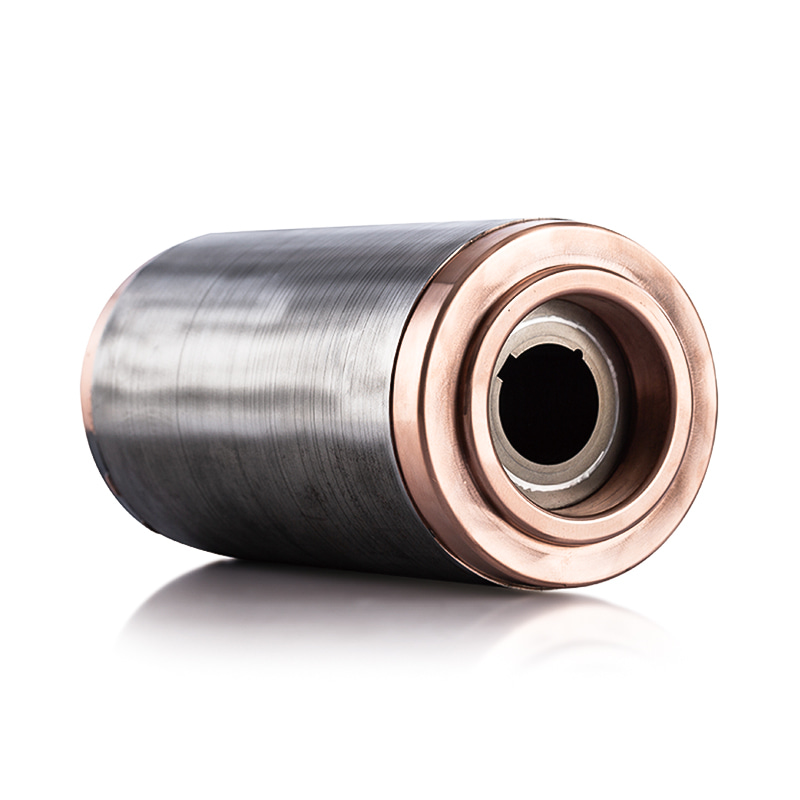
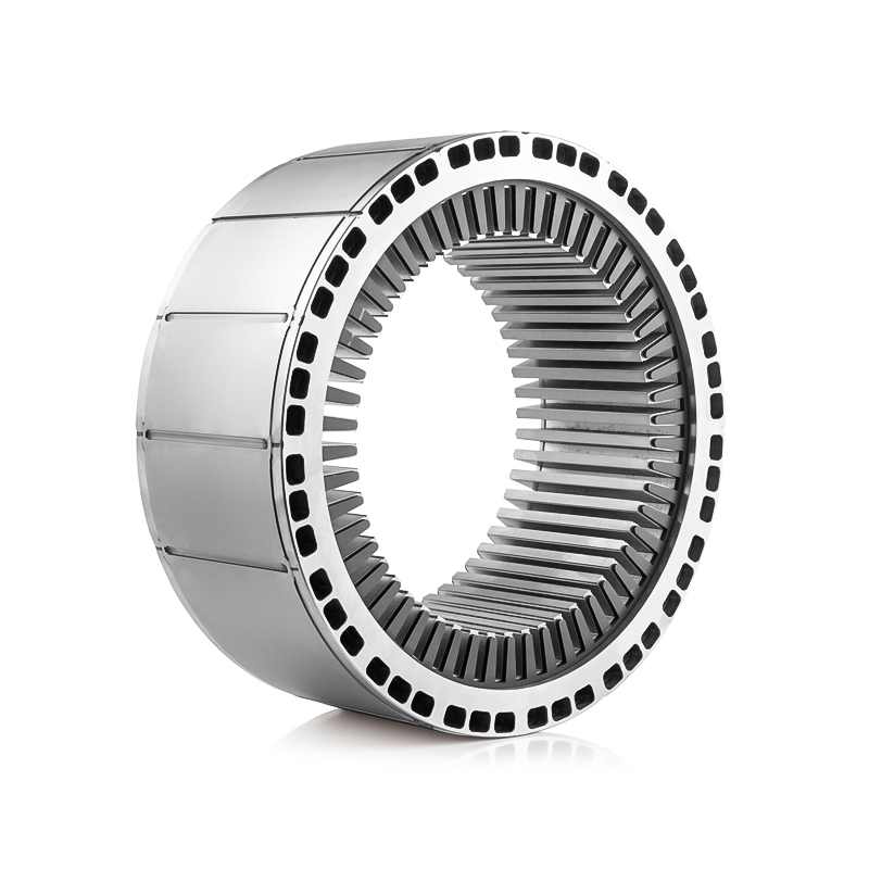
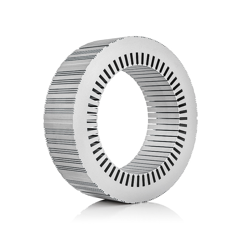
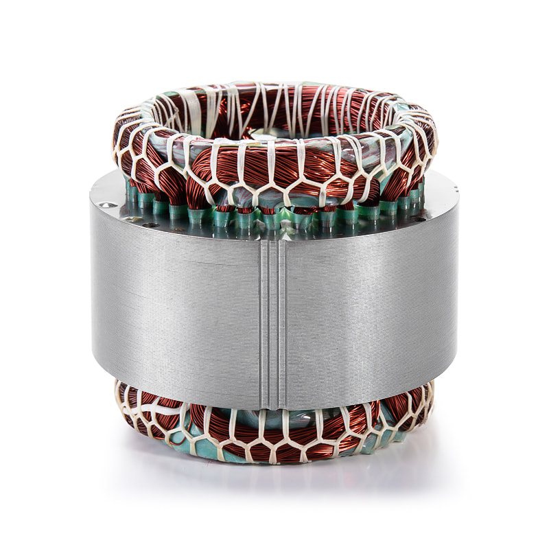
A stator core is not a single block of steel. It is a cylindrical stack of thin, insulated laminations that are stamped, stacked, and joined together to form a precise magnetic circuit. Because the core sits at the heart of electromagnetic energy conversion, every stage of its production leaves a measurable mark on the finished motor.
Here is the conclusion up front: the manufacturing process of stator core laminations is built on four pillars: material selection, precision stamping, controlled stacking, and a chosen fastening method. Within those pillars, the steel grade, die quality, stamping speed, and core assembly method create clear differences in efficiency, noise, and cost. Understanding these steps helps engineers and procurement teams evaluate suppliers and specify cores with confidence.
Material Selection Sets the Performance Ceiling
The performance of a lamination stack is mostly decided before the press ever runs. Non-oriented electrical steel, also called silicon steel, is the standard choice because its silicon content raises electrical resistivity and suppresses eddy current losses in a rotating field. The insulation coating applied to the steel surface, normally an inorganic or semi-organic layer, prevents current from flowing between adjacent laminations when they are stacked.
For high-frequency applications such as EV traction motors, thinner laminations are preferred. A 0.20 mm to 0.25 mm lamination reduces eddy current loss more effectively than the 0.35 mm to 0.50 mm material commonly used in industrial and appliance motors. Nickel-iron alloys appear in servo and precision motors where maximum magnetic permeability justifies a significantly higher material cost.
| Material | Silicon or nickel content | Typical thickness | Common applications |
|---|---|---|---|
| Non-oriented electrical steel | 2.0-3.2% silicon | 0.35-0.50 mm | Industrial motors, home appliances, pumps |
| High-grade non-oriented electrical steel | 3.0-3.5% silicon | 0.20-0.30 mm | EV drive motors, high-efficiency machines |
| Nickel-iron alloy | About 48% nickel | 0.10-0.20 mm | Servo motors, precision frequency-sensitive devices |
The trade-off between magnetic performance and cost is real. Thinner material improves efficiency but increases stamping difficulty and scrap sensitivity. For this reason, material selection is a joint decision between the motor designer and the core manufacturer.
Stamping: the Step That Controls Geometry and Burr
The majority of stator and rotor laminations are produced with progressive dies on high-speed presses. In a progressive die, a continuous strip of electrical steel advances through several stations. Pilot holes are punched first, then the slot geometry, and finally the outer contour is blanked. The rotor lamination is usually taken from the inner part of the strip, while the stator lamination uses the outer ring, a nesting arrangement that keeps material waste low.
Modern high-speed presses can deliver several hundred strokes per minute, which is what makes high-volume lamination production economical. The same die can also coin mechanical interlocking dimples into each lamination. When the laminations are later pressed into a stack, those dimples lock into the dimples of the neighboring lamination, creating a self-supporting core without any additional fastener.
Burr height is the most important quality characteristic at this stage. Many motor specifications hold burrs to 0.03 mm to 0.05 mm. Worn or misaligned dies produce larger burrs that penetrate the insulation layer and allow adjacent laminations to short-circuit. The result is increased core loss and hot spots that can shorten motor life. Reliable suppliers measure burr height regularly and replace tooling on a defined schedule.
Stacking and Joining Methods
Once laminations are punched, they must be stacked to the exact length of the core and joined. The joining method directly changes the mechanical strength, the stacking factor, and the eddy current behavior of the core.
Interlocking
Interlocked cores rely on the dimples coined during stamping. As each lamination is placed on the stack, its dimples snap into the recesses of the one below, and a final press operation compresses the whole stack to the target height. Interlocking is clean and fast, which makes it the default for appliance motors, small automotive motors, and many industrial types. The small gaps left by the dimples slightly reduce the stacking factor, but the mechanical result is usually sufficient.
Welding
When a core needs higher mechanical strength, welding is a common choice. One or several weld seams are run along the outer diameter of the stator core or the inner diameter of the rotor core. The welds create local short circuits, so the seam count and depth are controlled to minimize unwanted eddy current paths. Welded cores are typical in larger industrial motors and generators.
Adhesive Bonding
Adhesive bonding, often called core bonding, applies a thin resin layer between laminations and cures the stack into a rigid block. Bonded cores offer the best vibration damping and avoid weld-induced short circuits entirely. The process adds curing time, but the payoff is lower noise and stable geometry, which is why bonded cores are increasingly used in premium EV motors and servo applications.
Some manufacturers also use loose stacking, where laminations are simply compressed inside a motor housing or shrink-fit into a frame. This approach is economical for long core lengths, but it depends more on the final assembly process of the motor manufacturer.
Post-Processing, Inspection, and the Metrics That Matter
Stress-relief annealing is one post-processing option for laminations that have lost magnetic performance during stamping. The stamping process deforms the steel edges and introduces internal stresses that increase core loss. Annealing restores the grain structure, but it also destroys the insulation coating, so the laminations must be recoated afterward. This makes annealing an expensive step that is applied selectively.
The final quality plan usually includes stack height, parallelism, burr height, and surface condition checks. The stacking factor is the most informative number: it compares the actual steel volume in the stack with the apparent volume of the core. A typical stacking factor of 0.95 to 0.97 means the core is 95% to 97% steel and the rest is insulation and air. Lower values mean less magnetic material in the same physical length, which reduces torque density.
| Inspection item | Typical method | Acceptance example |
|---|---|---|
| Burr height | Optical profile measurement | Up to 0.03-0.05 mm |
| Stack height | Micrometer or CMM | Plus or minus 0.05 mm vs. drawing |
| Stacking factor | Weight and volume calculation | 0.95-0.97 |
| Parallelism | Surface plate and dial gauge | Up to 0.03 mm |
What to Look for in a Lamination Supplier
The process is only as good as the supplier's ability to repeat it. When auditing a stator core manufacturer, look for documented die maintenance, daily burr checks, and in-house measurement equipment that covers both dimensional and magnetic characteristics. A supplier that controls stamping parameters and stack height with data is far more likely to deliver consistent cores across production batches.
Application experience also matters. High-volume EV drive motor programs demand thin laminations, high stacking factors, and tight flatness control, which is why dedicated production lines for electric-vehicle drive motor stator and rotor cores have become a standard purchasing category. Industrial applications usually prioritize welded cores and dimensional stability, so the evaluation of industrial drive motor stator and rotor cores focuses on mechanical strength and repeatability over large batches. For appliances, cost consistency and long-run repeatability dominate, and that is the typical focus when qualifying home appliance motor stator and rotor cores.
 Home Appliance Motor Stator/Rotor Core Manufacturers, SuppliersZhejiang Jufeng Technology Co., Ltd. is China Home Appliance Motor Stator/Rotor Core Manufacturers and OEM/ODM Suppliers, we Custom Home ...View Product →
 Industrial Drive Motor Stator/Rotor Core Manufacturers, SuppliersAs China Industrial Drive Motor Stator/Rotor Core Manufacturers and OEM/ODM Suppliers, Zhejiang Jufeng Technology Custom Industrial Drive...View Product →
 Electric Vehicle Drive Motor Stator/Rotor Core Manufacturers, SuppliersAs China Electric Vehicle Drive Motor Stator/Rotor Core Manufacturers and Suppliers, Zhejiang Jufeng Technology provide OEM/ODM Electric ...View Product →
When you are ready to define a specification, contact our engineering team with your stack length, material requirement, and expected annual volume. If you are still at the design stage, a review of automotive motor stator and rotor cores design and material considerations can help you avoid common specification mistakes.
The manufacturing process of stator core laminations is where material science, tooling precision, and assembly discipline come together. Motors built on well-controlled lamination processes run cooler, quieter, and longer. Checking these details before you approve a supplier is one of the most effective ways to protect the performance you promised to your own customers.
Previous article
Why Is a Stator Core Made of Laminated Steel? Eddy Current Loss Explained
next article
Generator Stator Core Material: How to Choose the Right Electrical Steel for Efficiency
Related News
-
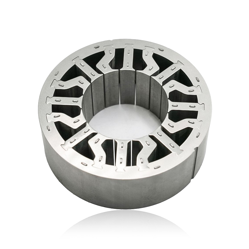
What are Stator and Rotor Cores? Stator Cores A stator core is the stationary component of an electric motor. It's the part that houses the copper windings, which, when an electric current passes thro...
See Details -
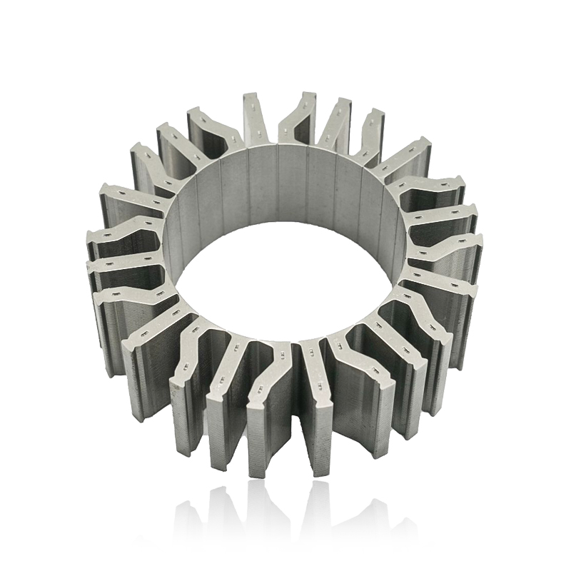
Introduction The modern automobile is a complex machine, and its evolution has been driven by continuous innovation in every component. While internal combustion engines have dominated the industry fo...
See Details -
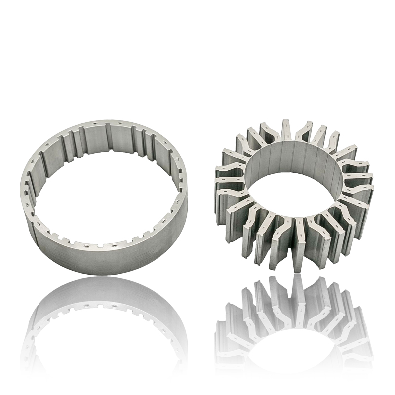
The Importance of Material Selection for Rotor and Stator Cores in Electric Vehicle Motors In the design of electric vehicle (EV) motors, material selection is a pivotal factor influencing the motor’s...
See Details -
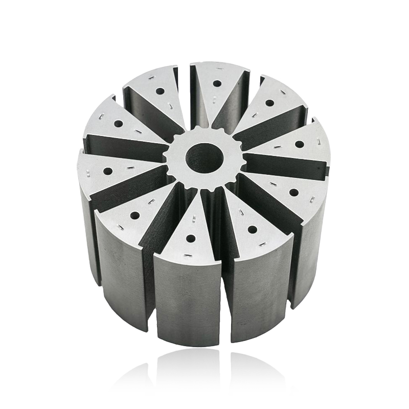
Introduction of automotive motor stator and rotor cores The increasing popularity of electric vehicles and hybrid electric vehicles has brought about significant advancements in automotive technology....
See Details


Zhejiang Jufeng Technology Co., Ltd. © All rights reserved
