
 简体中文
简体中文 English
 русский
 Español
Home / News / Industry News / Motor core lamination process: Applications, Selection Criteria, and Practical Guidance
Motor core lamination process: Applications, Selection Criteria, and Practical Guidance
Motor Core Lamination Process: From Steel Coil to Inspected Stack
Blanking, stacking and bonding decisions decide core loss, dimensional accuracy and the real cost of every motor you build.
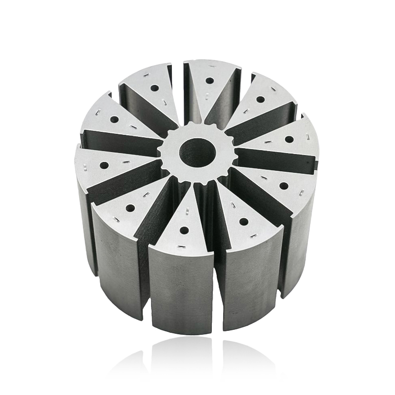
A 0.35 mm silicon steel coil goes into the press, and a few press strokes later it comes out as an interlocked stator stack for a traction motor. Everything that determines whether that stack performs as designed – burr height, stacking factor, layer-to-layer insulation, interlock consistency – is settled inside that window, long before the first winding goes in.
So here is the honest summary: the motor core lamination process is not one technology. It is a chain of small, measurable decisions. Handle them well and the core quietly does its job for a decade. Handle them badly and the losses reappear later as heat, noise and unbalanced current, usually in a design review nobody enjoys.
What the Lamination Process Is Actually Controlling
Every lamination in a stacked core is separated from its neighbours by a thin insulating layer – coating, oxide or adhesive – which breaks the path that circulating eddy currents would otherwise use. That single idea drives the whole process. Thinner steel cuts eddy current loss, but more layers mean more punching strokes, more stacking operations and more chances for a handling defect.
The practical bands are well established. Roughly 0.50 mm laminations suit general industrial and appliance motors, 0.35 mm is common in traction and higher efficiency machines, and 0.20 to 0.27 mm appears in high speed or high frequency designs. Moving from 0.50 mm to 0.35 mm raises the number of laminations in a fixed stack length by roughly forty percent, and every one of them has to be flat, clean and correctly stacked.
In a lamination line, hitting the dimension is rarely the hard part. Holding that dimension at hour six of a running shift, on the last third of the coil, is the hard part.
Step by Step: How a Laminated Core Is Built
The sequence below is the mainstream route. Shops merge or skip steps, but the dependencies stay the same.
- Coil preparation and slitting. Width tolerance and slit edge quality carry straight into the die, so a rough slit edge becomes a burr problem two stations later.
- Blanking and precision stamping. Progressive dies run high volume; compound or single-hit dies serve lower volumes and prototypes. Die clearance and tool sharpness set burr height and edge condition.
- Deburring. Brushing or controlled die clearance brings burrs under the specified maximum before stacking begins.
- Stress relief annealing. Punching strains the grain structure near the cut edge and degrades magnetic properties. Annealing recovers much of that, at the cost of an extra thermal step and possible insulation changes.
- Stacking and bonding. Interlocking, welding, adhesive bonding or riveting, with control of stack length, squareness and twist.
- Sizing and inspection. The stack is pressed to final height, then checked for burr height, dimensions, stacking factor and interlaminar resistance.
For a closer look at how those steps are held under control in production, including material and quality checks, see this walkthrough of how stator core laminations are manufactured.
Annealing is not automatically better. For some grades and stack designs, the extra handling and insulation risk costs more than the magnetic gain, which is why the choice belongs with the motor designer rather than the press shop alone.
Stacking and Bonding Methods Compared
Once the laminations are punched, the method used to hold them together decides a surprising amount about the finished core.
| Method | Typical fit | Effect on the stack | Main risk |
|---|---|---|---|
| Interlock (self-clinching) | High-volume appliance, tool and small motors | Fast, tool-free, no cure cycle | Dimples reduce effective steel area and stacking factor |
| Laser welding | Traction, servo and larger cores | Rigid, no interlock loss | Local heat can alter magnetic properties near the weld |
| Adhesive bonding | Thin laminations, low-volume and prototype runs | No tooling, good stacking factor | Cure cycle and bond line control before handling |
| Rivets or through pins | Large generator and industrial cores | Simple, serviceable, size tolerant | Extra holes reduce magnetic cross-section |
Tolerances and Faults That Decide Acceptance
Core specifications cluster around a small set of numbers. Burr height is usually capped between 0.02 mm and 0.05 mm depending on motor class and insulation system. Stacking factor typically lands between 0.95 and 0.98, with interlocked stacks at the lower end because the dimples displace steel. Stack length and squareness are commonly held within a tenth or two of a millimetre on traction and servo cores, and rotor cores add concentricity and dynamic balance on top of that.
- Burrs tall enough to bridge the interlaminar insulation, creating local short circuits and hot spots.
- Thickness variation across the coil, which shifts stack height and forces operators to compensate mid-run.
- Over-formed interlock dimples that cut usable steel area.
- Coating damage or contamination from handling, storage or deburring.
- Twist, camber and loose layers that survive visual inspection but fail once the stack is pressed or wound.
A stack can measure perfectly and still fail electrically. If burr height, coating integrity and interlaminar resistance are missing from the inspection plan, dimensional pass rates give a misleading picture of quality.
Matching the Lamination Process to the Application
Traction motors set the tightest combination of thin material, high stacking factor and dimensional control. Material in the 0.20 to 0.35 mm range is typical, and bonding or welding usually replaces interlocking because the core has to stay rigid at high speed with low loss.
Wind power generator cores flip the priorities. Diameters can be measured in metres, so segmenting, alignment and transport matter more than press speed; welded or bolted stacks hold up better than interlocked ones at that scale.
Appliance and power tool motors live at the opposite end. Volumes are enormous and cost per core dominates, so 0.5 mm material, interlocking and a progressive die with long tool life are the normal answer. Die maintenance intervals become a production planning question rather than a technical one.
Servo and rail transit cores sit between these extremes: moderate volumes, but tight slot geometry and low vibration requirements that keep slot profile, punch wear and lamination consistency under constant scrutiny.
Supplier Qualification: Questions Worth Asking Before Tooling Is Cut
The process is largely fixed once the die is cut, so most of the leverage sits in the weeks before. A handful of questions separates suppliers who understand the process from those who only quote a price per piece.
- What burr height is measured, on how many parts, and at which points along the coil?
- How is stacking factor verified on the finished stack rather than calculated from theory?
- How is coating integrity or interlaminar resistance checked after deburring and stacking?
- What are the first-off and last-off procedures when a coil or a die changes?
- Is core loss tested on a sample basis, and by which method – Epstein, single sheet or a stack test?
- Who owns the die, and what is the scheduled maintenance interval in strokes?
Suppliers who answer with measured data, sampling plans and named responsibilities are usually the ones whose cores still hold tolerance at month twelve of a program, not only at first article approval.
Bringing the drawing, the loss budget and the expected annual volume into the first technical conversation shortens the loop considerably – you can send the core drawing to the process team before the die design is frozen.
The motor core lamination process rewards the boring disciplines: correct die clearance, controlled burr height, a verified stacking factor, and inspection that checks insulation rather than only dimensions. Thickness and bonding choices follow from the application – thin and bonded for traction, thicker and interlocked for appliances, welded or bolted at generator scale. Settle those items early, with the people who will actually run the press, and the core stops being a risk item on the schedule.
Previous article
No more
next article
BLDC Silicon Steel Stator Core: Grade, Lamination Thickness and Sourcing
Related News
-
What are Stator and Rotor Cores? Stator Cores A stator core is the stationary component of an electric motor. It's the part that houses the copper windings, which, when an electric current passes thro...
See Details -
Introduction The modern automobile is a complex machine, and its evolution has been driven by continuous innovation in every component. While internal combustion engines have dominated the industry fo...
See Details -
The Importance of Material Selection for Rotor and Stator Cores in Electric Vehicle Motors In the design of electric vehicle (EV) motors, material selection is a pivotal factor influencing the motor’s...
See Details -
Introduction of automotive motor stator and rotor cores The increasing popularity of electric vehicles and hybrid electric vehicles has brought about significant advancements in automotive technology....
See Details


Zhejiang Jufeng Technology Co., Ltd. © All rights reserved
