
 简体中文
简体中文 English
 русский
 Español
Home / News / Industry News / Generator Stator Core Material: How to Choose the Right Electrical Steel
Generator Stator Core Material: How to Choose the Right Electrical Steel
Generator Stator Core Material: The Decision That Fixes Your Losses for a Decade
Choose by frequency first, then by flux density, then by lamination thickness. Coating class, punching quality and stacking method decide whether the strip you bought behaves like the steel you tested.
A stator core does three jobs at once. It carries the flux that links the rotor to the windings, it holds the slot geometry that locates the winding, and it keeps the air gap concentric through years of thermal cycling. Material choice sets the budget for all three, and the bill usually arrives at full-load thermal test rather than at drawing review.
Steel is rarely the most expensive line in the bill of materials. The losses it generates are. That is why the grade should be argued in watts, not in price per kilogram.
What the Material Has to Deliver
A stator core must be magnetically open to the flux travelling around the yoke and through the teeth, and magnetically closed to the alternating field that would otherwise drive eddy currents inside the steel. Alloying and laminating are the two standard ways of resolving that contradiction.
- Saturation polarization: the ceiling on flux density before the steel stops behaving like a good magnetic path.
- Specific core loss in W/kg, quoted at a stated polarization and frequency.
- Permeability at the working flux density, which sets the magnetizing current the machine needs.
- Resistivity, which suppresses eddy current loss and falls as silicon content falls.
- Stacking factor, the share of the core volume that is actually steel rather than coating and air gaps.
- Punchability, because a good magnetic grade that tears during blanking is not a good grade.
In a quotation, loss at the working point and stacking factor usually dominate. Permeability matters most where the air gap is small and the magnetizing budget is tight.
Non-Oriented Electrical Steel Is Still the Default
Non-oriented silicon steel remains the right answer for the large majority of generator stator cores. Silicon content between roughly 1.0% and 3.5% raises resistivity and cuts eddy current loss, while the grain structure stays random so the properties hold in every direction of the core.
| Lamination thickness | Silicon content | Practical frequency band | Where it fits |
|---|---|---|---|
| 0.65 mm | 1.0-1.5% | Up to 60 Hz | Large low-speed hydro and wind cores, where stacking cost dominates |
| 0.50 mm | 1.5-2.5% | 50-150 Hz | Standby alternators, diesel gensets and medium-speed machines |
| 0.35 mm | 2.5-3.2% | 150-400 Hz | High-speed generators and automotive auxiliary machines |
| 0.20-0.27 mm | 3.0-3.5% | 400 Hz and above | Very high speed cores where loss per kilogram is the binding constraint |
Two cautions follow. Thinner strip at higher silicon lowers loss but costs more per kilogram, wears tooling faster and reduces stacking factor, so the gain has to be measured against the stack height it adds. And a datasheet loss figure is measured on a standard sample: it is a comparison tool, not a prediction for your core.
When Non-Oriented Steel Is Not Enough
Some designs push past what standard silicon steel can deliver, usually because frequency, flux density or mass constraints are unusually aggressive.
- Electromagnetic pure iron: saturation near 2.1 T with excellent permeability, but low resistivity limits it to thin gauges or DC-biased magnetic circuits.
- Iron-cobalt alloys: saturation in the 2.3-2.4 T range, the highest among commercial soft magnetic materials, used where mass and volume are critical.
- Soft magnetic composites: coated iron particles pressed to shape, enabling three-dimensional flux paths at the cost of lower permeability and higher hysteresis loss.
- Amorphous and nanocrystalline ribbon: very low loss per kilogram at high frequency, but a stacking factor near 0.8 keeps it in small cores.
Core loss is quoted at the polarization and frequency the mill chose for its datasheet. Your generator runs at the polarization and frequency your design chose. The distance between those two points is where surprises live.
Four Decisions, in Order
Work through these in sequence and stop when the cost curve flattens.
- Operating frequency. It drives the eddy current component of loss and therefore sets the thickness ceiling before anything else is considered.
- Flux density and saturation headroom. Leave margin above the working point, particularly in machines that see transient overload or field forcing.
- Loss budget in watts. Convert W/kg into total core loss for the real stack and compare it with the efficiency target, not with someone else's curve.
- Manufacturing route and supply. Debating a 0.35 mm grade is pointless if the required width or coating sits on a twelve-week lead time.
Where those decisions land depends on the machine, and a generator stator core material selection guide with worked comparisons is usually faster than repeating the exercise from first principles.
Info: Ask for loss data at the polarization you actually run. A figure of 3.6 W/kg at 1.0 T and 50 Hz says very little about a core running at 1.6 T and 400 Hz.
Thickness, Coatings and the Tolerances That Bite
Surface insulation is what makes lamination work. Organic coatings are thin, weldable and inexpensive but limit annealing temperature; semi-organic and inorganic coatings tolerate stress relief annealing and give higher inter-laminar resistance, at some cost in stacking factor and tool wear.
Whatever the grade, these values belong in the drawing rather than in a mill default.
- Burr height after blanking, typically held below 0.05 mm to limit inter-laminar shorts.
- Coating insulation resistance per unit area, specified rather than assumed.
- Thickness tolerance, commonly plus or minus 0.01 mm on 0.35-0.50 mm strip.
- Flatness and camber, which decide whether automatic stacking runs at speed or stops for adjustment.
- Stacking factor, normally between 0.95 and 0.98 depending on thickness and coating.
Warning: Laser cutting leaves a heat-affected zone along the cut edge, and interlocking or welding creates local short circuits between laminations. Either choice can be correct, but core loss must be measured on a core built the production way.
Matching the Grade to the Machine
Generator families differ enough that a single grade recommendation misleads more than it helps.
Wind and hydro generators
Large diameters, low speed and high pole counts shift priority to stacking cost, handling and concentricity. Non-oriented steel at 0.50-0.65 mm with a semi-organic coating is common, and loss per kilogram is rarely the deciding number.
Standby and industrial alternators
Fixed 50 or 60 Hz operation, mature designs and severe price pressure: 0.50 mm fully processed non-oriented steel with a standard organic coating usually wins, and the effort goes into stacking factor and scrap rate instead of exotic grades.
High-speed and automotive generators
Once frequency climbs past a few hundred hertz, eddy loss grows faster than hysteresis loss and thickness becomes the dominant lever. Thin, high-silicon strip with an inorganic coating that survives annealing is the usual starting point.
Qualification and Testing Before Volume Release
Material certificates prove the strip, not the core. Both need verification.
- Mill certificate stating loss at your polarization and frequency, with the test standard named.
- Coating type and coating weight recorded alongside insulation resistance per unit area.
- Stacking method agreed, with loss measured on a sample core built the production way.
- A second source qualified in parallel, especially for thin gauges and inorganic coatings.
A core that holds its loss at 1.05 times rated flux, at rated frequency, after three thermal cycles is normally ready for prototype release. Anything that passes only on paper is not.
Generator stator core material is a compromise between loss, saturation, manufacturability and supply. The grade that wins on loss per kilogram is rarely the grade that wins on total cost, and the difference almost always hides in stacking factor, tool wear and scrap rate.
Revisit the choice whenever frequency, flux density or stack length changes. If you have a drawing and an annual volume, send both to our engineering team and we will come back with a grade recommendation and a stack design that can actually be built at volume.
Previous article
Generator Stator Core Construction: Laminations, Stacking and Cooling Explained
next article
The Role of Stator Core Laminations: Efficiency, Heat, Noise & Sourcing
Related News
-
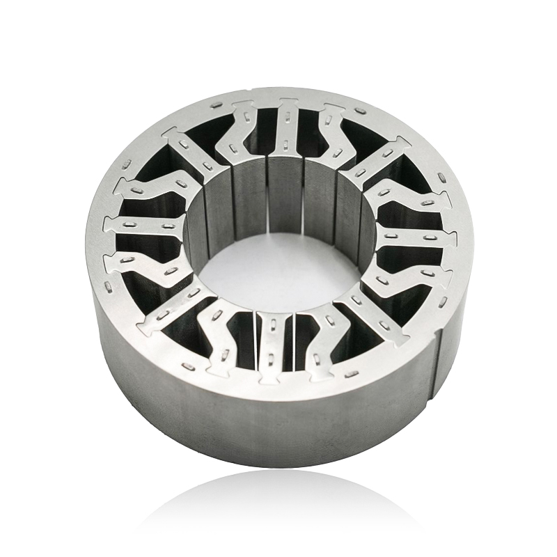
What are Stator and Rotor Cores? Stator Cores A stator core is the stationary component of an electric motor. It's the part that houses the copper windings, which, when an electric current passes thro...
See Details -
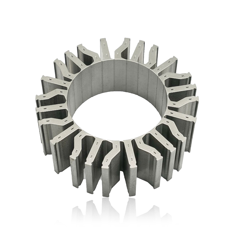
Introduction The modern automobile is a complex machine, and its evolution has been driven by continuous innovation in every component. While internal combustion engines have dominated the industry fo...
See Details -
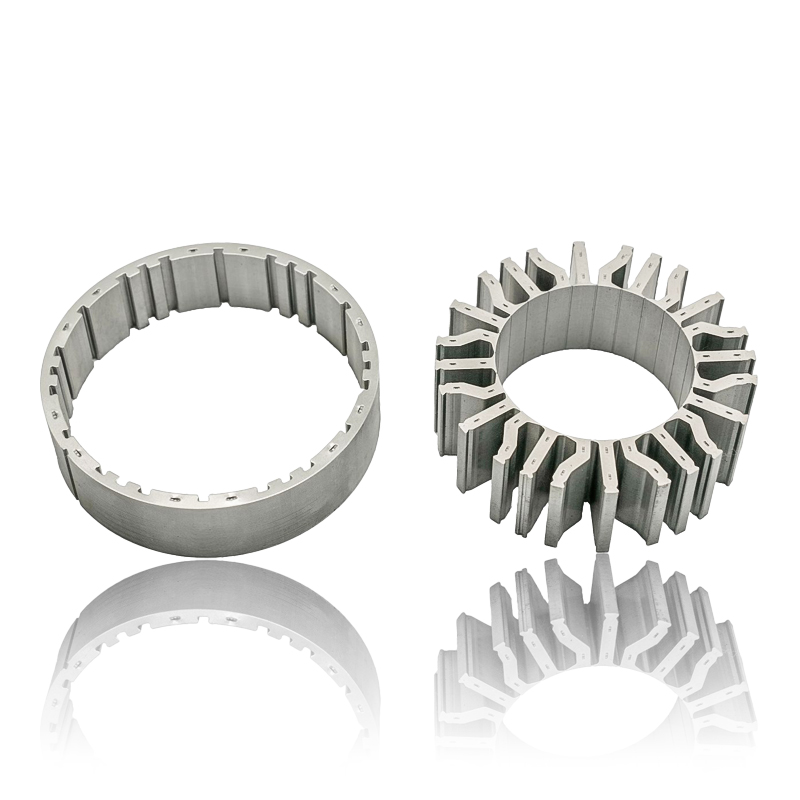
The Importance of Material Selection for Rotor and Stator Cores in Electric Vehicle Motors In the design of electric vehicle (EV) motors, material selection is a pivotal factor influencing the motor’s...
See Details -
Introduction of automotive motor stator and rotor cores The increasing popularity of electric vehicles and hybrid electric vehicles has brought about significant advancements in automotive technology....
See Details


Zhejiang Jufeng Technology Co., Ltd. © All rights reserved
