
 简体中文
简体中文 English
 русский
 Español
Home / News / Industry News / Generator Stator Core Construction: Laminations, Stacking and Cooling Explained
Generator Stator Core Construction: Laminations, Stacking and Cooling Explained
Generator core engineering
Generator Stator Core Construction: Laminations, Stacking and Cooling
Two suppliers can quote the same electromagnetic design and still deliver cores that differ in no-load loss, noise and temperature rise. The difference is construction: the steel, the clamping, the cooling.
In a large hydro or turbo generator, the stator core alone can weigh over a hundred tonnes of stacked steel. Long before anyone argues about the winding, that stack has decided how much input energy becomes heat, how loudly the machine hums, and how evenly the air gap holds over decades of service.
Construction comes down to four linked decisions: lamination grade and thickness, punching and slot geometry, stacking and clamping method, and the ventilation path. Each has a cost side and a loss side, and a thinner lamination only pays off when coating quality and stacking factor are good enough to keep the slot area you paid for.
How a generator stator core is assembled
The build sequence is short, but each step constrains the next one.
- Punching or laser cutting. Laminations are cut from coated electrical steel. Slot geometry, tooth width and burr height are fixed here, and a burr that bridges the coating creates a local short between sheets.
- Insulation coating. Oxide or C-type insulation sets interlaminar resistance: too thin and the stack behaves like one solid block, too thick and the stacking factor drops.
- Stacking. Laminations are stacked in register on dovetail key bars in large machines, or interlocked in the die for small ones.
- Compression and clamping. End plates and pressure fingers, or through-bolts, apply a defined specific pressure that holds the stack tight without crushing the coating.
- Ventilation features. Duct spacers, axial channels and stepped end packs are built in during stacking, not added afterwards.
- Verification. Bore, slots, stack length, clamping and core loss are measured before the winding comes near the frame.
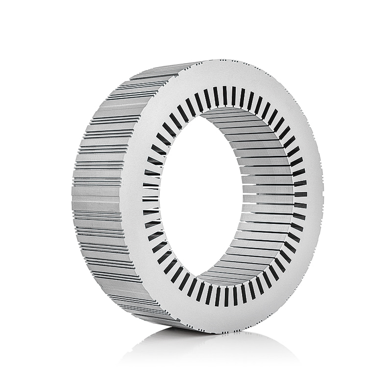
Small cores merge these steps: a progressive die punches and interlocks the laminations, and the stack is welded or bonded on the outside diameter. That removes cost rather than risk, moving the risk into tooling wear and coating consistency.
Lamination grade and thickness: the first loss lever
Electrical steel grades are named for their loss. In a designation such as M400-50A, the 400 means a maximum specific loss of 4.00 W/kg at 1.5 T and 50 Hz, and the 50 means 0.50 mm thickness. Change the trailing number and you change the eddy current component, which grows with the square of thickness and frequency.
| Thickness | Grade examples | Where it fits | What you trade |
|---|---|---|---|
| 0.65 mm | M600-65A, M800-65A | Small, low-frequency machines and light-duty alternators | Highest eddy loss per kilogram, but the lowest material and tooling cost |
| 0.50 mm | M400-50A, M470-50A | Mainstream 50/60 Hz structures, hydro, industrial and standby generators | Balanced loss and cost; the default unless efficiency targets demand more |
| 0.35 mm | M350-35A, M300-35A | High-efficiency and higher-frequency generators, wind and traction | Lower loss, higher cost per kilogram, more strokes, less forgiving coating |
| 0.20-0.27 mm | High-frequency grades | High-speed alternators and designs where frequency dominates loss | Lowest loss at frequency, but brittle edges and premium tooling |
Stepping up one grade, from M470-50A to M400-50A, removes roughly 15 percent of that lamination's specific loss. It is easy to give that gain back through a worse stacking factor, heavier coating or poorer burr control, which is why material and process should be quoted together. The material side is covered in this guide to choosing the right electrical steel for a generator stator core.
Info. The same M400-50A supplied with a damaged coating and heavy burrs can run hotter than a cleanly built M470-50A core of the same weight.
Stacking and clamping: where the core gets its mechanical identity
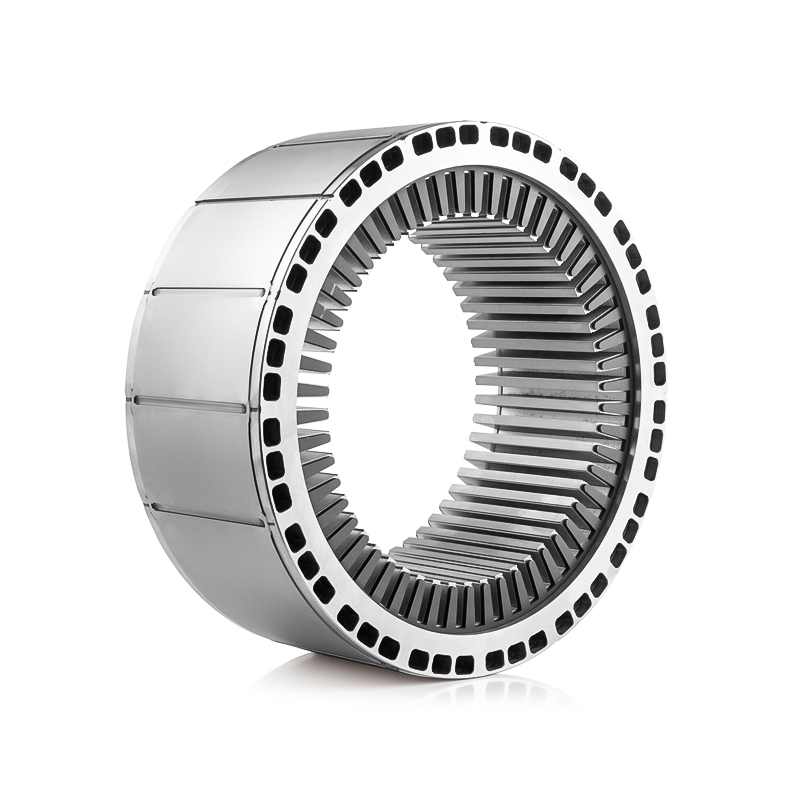
Laminations do not hold themselves in place. In large generator cores the stack sits in dovetail slots on key bars inside the frame, compressed by pressure fingers at both ends, with through-bolts or clamping plates maintaining end pressure. Smaller cores use interlocking, welding or bonding instead.
- Interlocked stacks. Fastest to build and self-aligning, but the interlock bridges form local magnetic paths between laminations.
- Welded stacks. Strong and economical on small and medium cores; the weld seams conduct between sheets, so weld position matters as much as weld strength.
- Bonded or varnish-cured stacks. Best interlaminar insulation and lowest loss, but they demand clean, flat laminations and a controlled curing cycle.
- Key bars, pressure fingers and through-bolts. The standard for large hydro and turbo generators, because end pressure can be set, measured and re-checked.
Two numbers show whether stacking was done properly: stacking factor, normally guaranteed between 0.94 and 0.98 for coated electrical steel, and the flatness and squareness of the finished stack. Below 0.94 you are buying air where the design assumed iron.
Warning. An under-compressed stack loosens in service and starts to fret; an over-compressed stack crushes the coating or bows the laminations, which appears later as bore eccentricity and an uneven air gap.
Cores that travel by road or sea are re-checked and re-torqued after the winding is fitted, because clamping has to survive transport as well as operation.
Ventilation and end-region detail
Heat leaves a stator core by conduction along the laminations into the frame, convection into the air gap, and forced flow through the core itself. Construction decides how much of each route you get.
In large machines the stack is divided into packs by radial ventilation ducts formed from duct spacers, commonly every 40 to 60 mm of stack length, with axial channels through the yoke where the cooling circuit needs them.
The end region is the difficult part. Stray flux from the end winding enters the core ends and the clamping structure, so end packs are stepped, built from progressively shorter laminations to reduce loss density. Get that detail wrong and the hottest point in the machine sits where no thermocouple was installed.
In most generator cores, the limiting temperature is not the average temperature of the stack. It is the tooth tip beside the air gap and the end lamination behind the pressure finger.
Danger. Deleting ventilation ducts to simplify stacking and lift the stacking factor is one of the quickest ways to create a hot spot that no shop-floor test will reveal.
Tolerances and inspection: proof that the construction works
Construction quality can be verified in the plant, before the winding is fitted. These are the checks that separate a core matching its calculation from one matching only its drawing.
| Check | Typical method | What it protects against |
|---|---|---|
| Stacking factor | Lamination count and stack height measurement | Lost slot area, higher flux density, reduced output |
| Bore diameter and roundness | Bore micrometer or laser measurement at several axial positions | Uneven air gap, unbalanced magnetic pull, vibration |
| Slot dimensions and pitch | Slot gauges and template checks across several teeth | Winding fit, thermal contact and stator stiffness |
| Interlaminar resistance | Franklin or surge test at a defined voltage | Shorts between laminations and local eddy current heating |
| Core loss | Ring flux or magnetising test on the assembled core | No-load loss higher than the design promised |
| Clamping tightness | Bolt torque check, tap test, vibration measurement | Loosening in service, fretting and progressive core damage |
Ask for records, not only results
Coating batch, punch tool life, stack pressure, curing cycle and ring test data together describe a process. A certificate on its own describes a document.
Matching construction to the generator type
The same rules lead to different answers depending on the machine.
- Large hydro generators. 0.50 mm or 0.35 mm grades, key-bar stacking, radial ducts, stepped ends and pressure fingers, built for decades of service.
- Direct-drive wind generators. High stacking factor and tight bore tolerance for air-gap uniformity, high-volume punching, bonded or interlocked stacks.
- Turbo generators. 0.35 to 0.50 mm high-strength grades, precise end-region cooling, and clamping that holds through continuous thermal cycling.
- Industrial and standby gen-sets. 0.50 mm grades, welded or interlocked stacks and simple duct layouts, with cost and lead time driving decisions.
- High-speed alternators. 0.20 to 0.27 mm grades, where frequency makes eddy loss dominant and punching precision matters more than stack length.
Success. The cheapest route to a loss target is usually better construction rather than thinner steel. A higher stacking factor, cleaner coating and tighter bore recover more than one grade step.
Slot geometry, duct pitch and stack pressure are cheap to adjust on a drawing and expensive to adjust in a die.
When a generator core goes out for quotation, the specifications that move the price most are rarely the ones in the drawing title block. Grade and thickness, stack length and stacking factor, clamping method, duct layout, bore and slot tolerances, and the expected duty cycle decide whether two quotes for the same core differ by twenty percent.
The practical sequence: fix the loss budget before the slot area, confirm the stacking factor you are buying, witness the core test, and keep the inspection records with the machine.
If the generator is still being designed, bring the core supplier in early. It is easier to agree a stacking factor, a duct pitch and a bore tolerance while the frame is a drawing than once the first prototype core is on the test bed. You can talk to our core engineers at any stage.
Previous article
No more
next article
Generator Stator Core Material: How to Choose the Right Electrical Steel
Related News
-
What are Stator and Rotor Cores? Stator Cores A stator core is the stationary component of an electric motor. It's the part that houses the copper windings, which, when an electric current passes thro...
See Details -
Introduction The modern automobile is a complex machine, and its evolution has been driven by continuous innovation in every component. While internal combustion engines have dominated the industry fo...
See Details -
The Importance of Material Selection for Rotor and Stator Cores in Electric Vehicle Motors In the design of electric vehicle (EV) motors, material selection is a pivotal factor influencing the motor’s...
See Details -
Introduction of automotive motor stator and rotor cores The increasing popularity of electric vehicles and hybrid electric vehicles has brought about significant advancements in automotive technology....
See Details


Zhejiang Jufeng Technology Co., Ltd. © All rights reserved
