 简体中文
简体中文 English
 русский
 Español
Home / News / Industry News / Exploring the Role of Automotive Motor Stator and Rotor Cores: A Complete Overview
Exploring the Role of Automotive Motor Stator and Rotor Cores: A Complete Overview
Introduction
The modern automobile is a complex machine, and its evolution has been driven by continuous innovation in every component. While internal combustion engines have dominated the industry for over a century, the shift towards electrification has placed a new emphasis on the heart of electric propulsion: the motor. Automotive motors, particularly those used in electric and hybrid vehicles, are marvels of engineering, and their efficiency and performance are critical to the overall functionality of the vehicle.
At the very core of these powerful motors lie two fundamental components: the stator and the rotor cores. Often overlooked, these metallic structures are far more than simple frames. They are the linchpin of the motor's operation, responsible for guiding the magnetic fields that convert electrical energy into the rotational motion that powers the wheels. The quality and design of these cores directly impact the motor's power density, efficiency, and overall reliability. This article will provide a comprehensive guide to automotive motor stator and rotor cores, delving into the materials they are made from, the intricate manufacturing processes, their diverse applications, and the exciting future trends that are set to redefine automotive motor technology.
What are Stator and Rotor Cores?
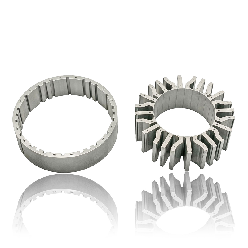
At the heart of every electric motor, whether a small fan motor or the high-power traction motor in an electric vehicle, are two primary components: the stator and the rotor. The cores of these components are the foundational structures that enable the motor's function.
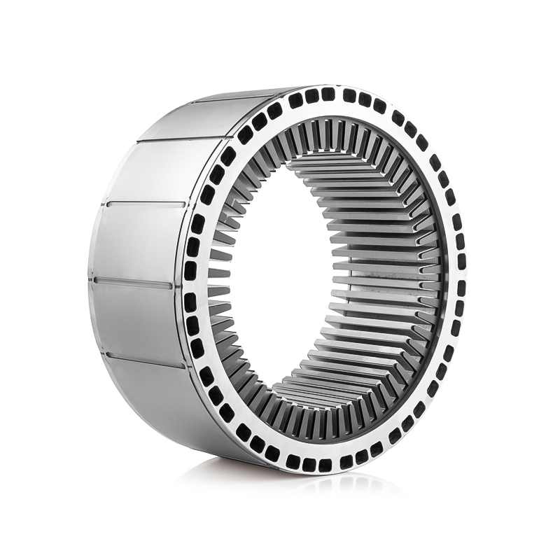
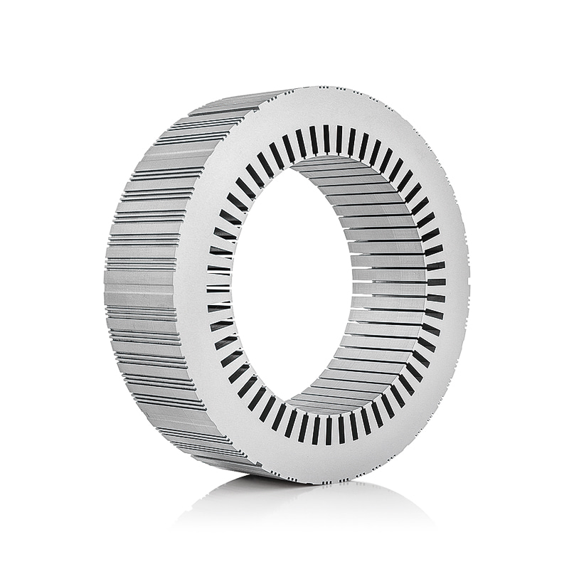
Stator Core
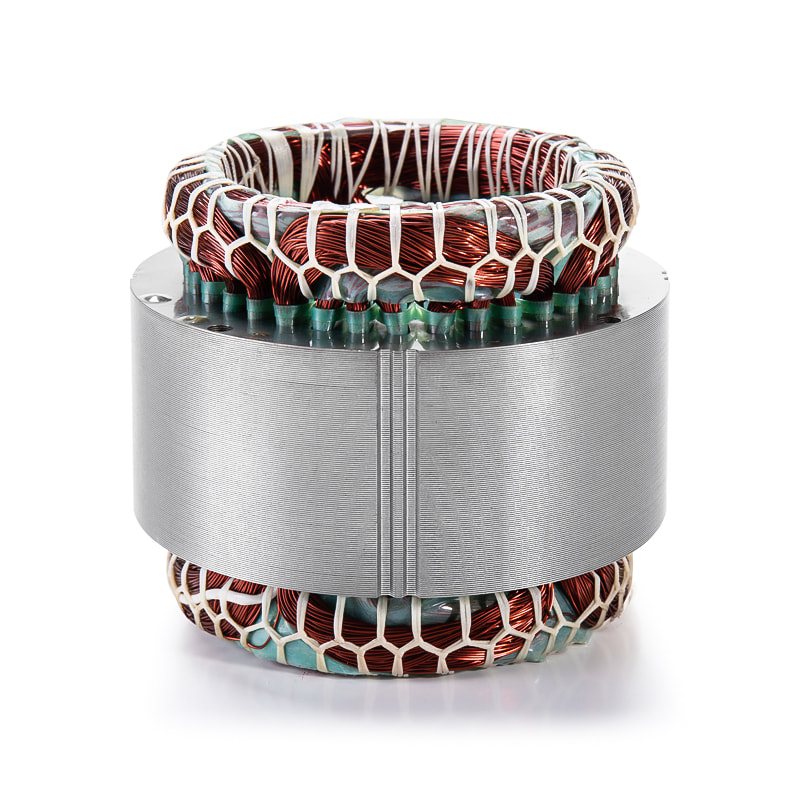
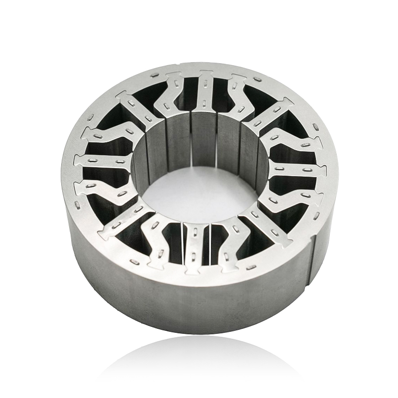
The stator core is the stationary part of the motor, a hollow cylindrical structure that houses the motor's windings. Its name, derived from "static," perfectly describes its role. The stator core is the anchor of the motor, and its primary function is to provide a stable, low-reluctance path for the magnetic flux generated by the stator windings.
Definition and Function: The stator core is a meticulously crafted assembly, typically consisting of a stack of thin, soft magnetic material laminations.These laminations are designed with slots around the inner perimeter into which the windings (coils of insulated wire, usually copper or aluminum) are placed. When an electric current flows through these windings, they create a rotating magnetic field. The stator core's role is to concentrate and direct this magnetic field, ensuring it is as strong and uniform as possible to efficiently interact with the rotor. Without a proper core, the magnetic field would be weak and dispersed, leading to a highly inefficient motor.
Role in Generating the Magnetic Field: The magnetic field is the very force that drives the motor. The stator core's geometry and material properties are critical in shaping and guiding this field. The high permeability of the core material allows it to be easily magnetized, thus concentrating the magnetic flux lines. The design of the slots and the overall shape of the core are optimized to create a smooth, rotating magnetic field that interacts with the rotor to produce continuous torque.
Common Materials Used: The most common and widely used material for stator cores is electrical steel, also known as silicon steel. This material is chosen for its excellent soft magnetic properties, including high magnetic permeability and, most importantly, low hysteresis and eddy current losses. These losses, collectively known as core losses, represent wasted energy in the form of heat and are a major factor in reducing motor efficiency. By using thin laminations of electrical steel, manufacturers can significantly reduce eddy currents and minimize core losses. The laminations are insulated from each other with a thin non-conductive layer to further suppress these currents. The shape of these laminations is precisely stamped from large sheets of steel, ensuring the final core has the exact geometry required for the motor's design.
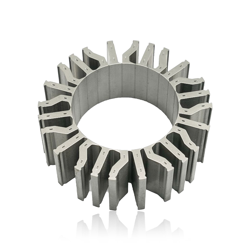
Rotor Core
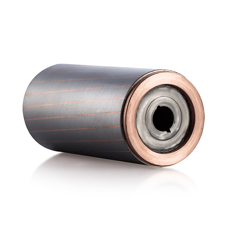
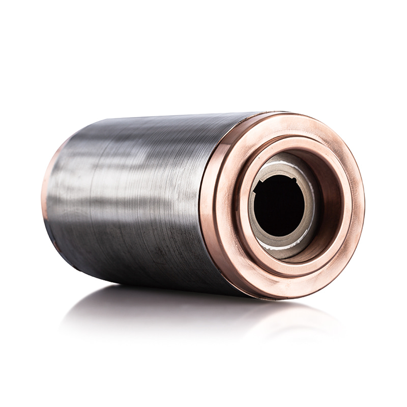
The rotor core is the rotating part of the motor, positioned inside the stator core and mounted on the motor's central shaft. It is the component that turns, converting the magnetic force into mechanical motion.
Definition and Function: The rotor core is also typically made from a stack of electrical steel laminations, though its design is fundamentally different from the stator's.The rotor's function is to react to the stator's rotating magnetic field. This interaction induces currents in the rotor, which in turn generate their own magnetic field. The attraction and repulsion between the stator's magnetic field and the rotor's magnetic field create the torque that causes the rotor to spin. The core provides the necessary low-reluctance path for the rotor's magnetic flux, just as the stator core does for the stator's field.
Role in Interacting with the Magnetic Field to Produce Torque: The rotor core is the workhorse of the motor. It is a critical part of the magnetic circuit. As the stator's magnetic field sweeps across the rotor, it "induces" a magnetic field in the rotor core and its associated windings or magnets. The interaction of these two fields produces a force that acts on the rotor, causing it to rotate. The continuous rotation of the stator's field leads to continuous rotation of the rotor, and this is how electrical energy is converted into mechanical work. The precise design of the rotor core, including the placement of its windings, magnets, or conductive bars, is essential for generating the desired level of torque and speed.
Types of Rotor Cores: The type of rotor core used depends on the motor design. Two common types in automotive applications are:
-
Squirrel Cage Rotor: This is a simple and robust design, common in induction motors. The core consists of a stack of laminations with slots that hold conductive bars (usually aluminum or copper) along their length. These bars are short-circuited at both ends by end rings, forming a structure that resembles a squirrel cage. The rotating magnetic field from the stator induces currents in these bars, creating the necessary magnetic field for torque production. This design is highly reliable and cost-effective.
-
Wound Rotor: Used in certain types of motors, the wound rotor core has slots that are filled with insulated windings, similar to the stator. These windings are connected to slip rings on the shaft, allowing external resistance or voltage to be applied to the rotor circuit. This design provides greater control over motor speed and torque characteristics but is more complex and expensive than the squirrel cage type.
In addition to these, permanent magnet rotors are widely used in modern electric vehicles. These rotors incorporate powerful permanent magnets on or inside the laminated core structure. The permanent magnets provide the rotor's magnetic field, and their strong, fixed flux density contributes to higher efficiency and power density compared to induction motors. The rotor core in these designs still provides the structural and magnetic path for the flux lines.
Materials Used in Automotive Motor Cores
The choice of material for stator and rotor cores is a critical design decision that directly influences the performance, efficiency, and cost of an automotive motor. The ideal material must possess a unique combination of magnetic and mechanical properties to meet the demanding requirements of electric and hybrid vehicles.
Electrical Steel
Electrical steel, often referred to as silicon steel or lamination steel, has been the cornerstone material for motor cores for over a century. It is a specialized iron alloy containing varying percentages of silicon, typically ranging from 1% to 6.5%. The addition of silicon is the key to its exceptional properties.
Properties and Advantages: The primary advantages of electrical steel are its high magnetic permeability and low core loss.
-
High Permeability: This property allows the material to be easily magnetized and to efficiently conduct and concentrate magnetic flux. A high permeability ensures that the magnetic field generated by the stator windings is effectively channeled through the core, minimizing the current required to produce the desired torque. This translates directly to higher motor efficiency and a better power-to-weight ratio.
-
Low Core Loss: Core losses are a form of energy inefficiency that manifest as heat. They are primarily composed of two components:
-
Hysteresis Loss: This is the energy lost during the repeated magnetization and demagnetization of the material as the magnetic field changes direction (in AC applications). The silicon content in electrical steel helps to reduce the size of the hysteresis loop, thereby minimizing this energy loss.
-
Eddy Current Loss: These are circular electrical currents induced within the core material by the changing magnetic field. They generate heat and are a significant source of energy waste. The use of thin laminations, insulated from each other by a thin coating, dramatically increases the electrical resistance in the direction perpendicular to the laminations, effectively blocking these currents and reducing eddy current loss.
-
Different Grades and Their Applications: Electrical steel is available in different grades, each with tailored properties for specific applications. The two main types are:
-
Non-Grain-Oriented (NGO) Electrical Steel: The crystalline grains in this steel are randomly oriented, giving it uniform magnetic properties in all directions (isotropic). This makes it ideal for the rotating magnetic fields found in motors, where the direction of the magnetic flux is constantly changing. NGO steel is the most common material for both stator and rotor cores in electric motors.
-
Grain-Oriented (GO) Electrical Steel: In this type, the crystalline grains are aligned in the rolling direction, providing superior magnetic properties in a single direction. While this makes it unsuitable for the isotropic flux in most motor applications, it is the material of choice for transformers where the magnetic flux path is predominantly linear.
The grade of electrical steel is also defined by its thickness and magnetic properties, often designated by standards like M15 or M19. Thinner grades are generally used in high-frequency applications, such as high-speed EV motors, to further reduce eddy current losses.
Considerations for Material Selection: Selecting the right grade of electrical steel involves a trade-off between magnetic performance, mechanical strength, and cost. Higher silicon content can improve magnetic properties but may make the material more brittle and difficult to process. The thickness of the laminations is also a key factor. Thinner laminations reduce core loss but increase the number of sheets required, which can drive up manufacturing costs.
Soft Magnetic Composites (SMC)
Soft Magnetic Composites (SMCs) represent a newer, highly promising class of materials that are challenging the dominance of traditional electrical steel laminations, particularly in complex motor designs. SMCs are made from insulated iron powder particles that are compacted and heat-treated to form a solid, three-dimensional core.
Properties and Advantages: SMCs offer a distinct set of advantages that address some of the limitations of electrical steel.
-
Isotropic Properties: Unlike electrical steel, which is anisotropic (properties vary with direction), SMCs have isotropic magnetic properties. This means that magnetic flux can be directed in three dimensions (3D) within the core, allowing for innovative motor designs that are impossible with 2D laminations. This design freedom can lead to more compact, higher power density motors, such as axial flux motors.
-
Design Flexibility: The powder metallurgy process used to create SMC cores allows for the net shaping of complex geometries with minimal material waste. This can eliminate the need for intricate stamping and stacking processes, simplifying manufacturing and reducing production costs. The ability to create complex shapes also enables motor designers to optimize the flux paths to reduce leakage and improve efficiency.
-
Low Eddy Current Loss at High Frequencies: Each iron particle in an SMC is insulated from its neighbors. This structure creates an inherently high electrical resistance throughout the core, significantly reducing eddy current losses, especially at the high operating frequencies of modern traction motors.
Applications in Complex Motor Designs: SMCs are particularly well-suited for high-speed motors and those with complex magnetic circuits, where the 3D flux path can be exploited for performance gains. They are finding increasing application in motors for electric bikes, scooters, and increasingly, in specialized auxiliary motors and traction motors for electric and hybrid vehicles where their unique properties can lead to significant improvements in power density and efficiency.
Manufacturing Processes
The transformation of raw materials into the highly precise and functional stator and rotor cores is a complex and multi-stage manufacturing process. The techniques used are crucial for achieving the desired magnetic properties, dimensional accuracy, and mechanical integrity required for high-performance automotive motors.
Lamination Stacking
The most common method for producing both stator and rotor cores, especially from electrical steel, is lamination stacking. This process involves the precision stamping and assembly of thin sheets of material.
Process of Creating Cores from Thin Laminations: The first step in this process is the preparation of the raw material, which comes in large coils of electrical steel. These coils are fed into a high-speed stamping press. A die, custom-designed to the exact specifications of the motor core, stamps out individual laminations, each with the precise outer diameter, inner bore, and slot geometry. The lamination thickness is a critical parameter, as thinner laminations are essential for reducing eddy current losses, particularly in high-frequency motor applications. After stamping, a thin, non-conductive insulation coating is applied to one or both sides of the lamination to electrically isolate them from each other.
Once the individual laminations are created, they are stacked on top of one another. The stacking process is automated and must be highly precise to ensure the slots and features of each lamination align perfectly. Misalignment can create stress points, reduce the effective magnetic cross-section, and compromise the motor's performance. The final stack can range from a few dozen to several thousand laminations, depending on the motor's design and size.
Bonding Methods: To hold the stack of laminations together as a single, rigid core, various bonding methods are employed:
-
Welding: The most common method for joining stator laminations is welding. Small, localized spot welds are applied along the outer or inner diameter of the stack. This creates a strong, permanent bond that can withstand the significant forces and vibrations within a motor. The welding process must be carefully controlled to avoid compromising the magnetic properties of the core material in the welded areas.
-
Adhesive Bonding (Backlack): In this method, a thermosetting resin (often referred to as "backlack") is pre-applied to the electrical steel sheet. After the laminations are stamped, the stack is heated under pressure. The heat activates the adhesive, bonding the laminations together into a single, monolithic core. This method provides a very rigid and robust structure and can improve the magnetic performance by minimizing the magnetic losses at the interfaces between laminations.
-
Interlocking (T-Shape, V-Shape): Some designs use mechanical interlocking features, such as tabs and slots, to hold the laminations together. This method is less common for large-scale automotive applications but can be used for smaller, specialized motors.
-
Riveting: Rivets can be passed through holes in the laminations and mechanically fastened. This is a simple but less-common method for modern automotive cores due to its potential to disrupt the magnetic flux path.
Precision and Quality Control: Throughout the lamination stacking process, meticulous quality control is paramount. Automated vision systems and sensors are used to check for burrs, cracks, or other defects in the stamped laminations. The stack height, alignment, and overall dimensional accuracy are continuously monitored to ensure the final core meets the tight tolerances required for motor assembly and optimal performance.
Powder Metallurgy (for SMC Cores)
The manufacturing of cores from Soft Magnetic Composites (SMCs) utilizes the advanced process of powder metallurgy, offering a different approach to core production.
Process of Compacting and Sintering SMC Powders: The process begins with a specially formulated soft iron powder. Each particle of this powder is coated with a thin, electrically insulating layer. This insulation is the key to achieving the low eddy current losses characteristic of SMCs. The insulated powder is then placed into a precision die cavity. A high-pressure press compacts the powder into the desired core shape. This is a critical step, as the compaction pressure directly influences the final density and mechanical strength of the part.
After compaction, the green (unsintered) part is carefully ejected from the die. It is then subjected to a heat treatment, or sintering, process. During sintering, the core is heated in a controlled atmosphere to a temperature below the melting point of the iron. This process strengthens the bonds between the individual powder particles and cures the insulating coating, but it does not melt the material. The sintering process is crucial for achieving the final mechanical strength and magnetic properties of the core.
Achieving Desired Density and Magnetic Properties: The final density of the SMC core is a key performance metric. A higher density generally leads to better magnetic properties, such as higher saturation magnetization, but can increase the overall cost. The powder formulation, compaction pressure, and sintering parameters are all carefully controlled to achieve the ideal balance of magnetic performance, mechanical strength, and manufacturing cost.
Winding and Assembly
Once the stator and rotor cores are manufactured, the final stages of motor production involve the winding of coils and the assembly of the components.
Process of Winding Coils: For the stator, insulated copper or aluminum wire is wound into the slots of the stator core. This can be a complex and highly automated process. There are two primary winding methods:
-
Distributed Winding: The coils are wound into multiple slots, creating a distributed winding pattern that improves the magnetic field distribution and reduces harmonic content.
-
Concentrated Winding: Each coil is wound around a single tooth of the stator core. This method simplifies the winding process and is often used in high-volume production.
After winding, the ends of the coils are connected and terminated, and the entire assembly is often impregnated with a varnish or resin to provide electrical insulation and enhance mechanical rigidity.
Assembly of the Rotor Core: The rotor core is carefully press-fitted or shrunk-fitted onto the motor's shaft. For permanent magnet motors, the magnets are then securely attached to the rotor core, either on the surface or embedded within the lamination stack. For squirrel cage rotors, the conductive bars are cast into the core and end rings are attached. The final assembled rotor is then balanced to ensure smooth and vibration-free operation at high speeds.
These sophisticated manufacturing processes, from the precision stamping of laminations to the advanced techniques of powder metallurgy, are what enable the production of the high-quality automotive motor cores that are essential for the next generation of electric and hybrid vehicles.
Applications in Automotive Motors
The demanding and diverse requirements of modern automotive systems have made high-performance electric motors indispensable. Stator and rotor cores are at the heart of these motors, and their design is specifically optimized for each unique application, from the high-power traction motors of electric vehicles to the smaller auxiliary motors in traditional cars.
Electric Vehicles (EVs)
In a pure Electric Vehicle, the motor is the sole source of propulsion. This makes the performance of its traction motor paramount to the vehicle's range, acceleration, and overall efficiency. Stator and rotor cores are the most critical components of these traction motors.
Stator and Rotor Cores in Traction Motors: EV traction motors must operate across a wide range of speeds and loads, from slow-speed, high-torque acceleration to high-speed, constant-power cruising. This demanding performance envelope places unique requirements on the motor cores.
-
High Efficiency: To maximize the vehicle's range, the motor must convert as much electrical energy from the battery into mechanical energy as possible, minimizing waste heat. This necessitates the use of high-quality electrical steel with very low core losses (hysteresis and eddy current losses). The thin laminations of the stator and rotor cores, along with advanced winding techniques, are designed to keep these losses to an absolute minimum.
-
High Power Density: A key goal for EV designers is to reduce the weight and size of the motor to improve vehicle dynamics and packaging. This requires a high power density—the ability to produce a large amount of power from a small and light motor. The cores play a vital role here by enabling high magnetic flux density and robust mechanical performance at high rotational speeds.
-
Thermal Management: EV traction motors often operate under high-stress conditions, generating significant heat. The stator and rotor cores must be designed to effectively dissipate this heat to prevent performance degradation and ensure motor longevity. The laminations themselves can be designed with cooling channels, and advanced materials and bonding methods are used to improve heat conduction.
The majority of modern EV traction motors utilize Permanent Magnet Synchronous Motors (PMSMs) due to their superior efficiency and power density, especially in urban driving cycles. In these motors, the rotor core houses powerful rare-earth permanent magnets, while the stator core, made of high-grade electrical steel, is responsible for generating the strong, rotating magnetic field that interacts with the permanent magnets to produce torque. The design of both the stator and rotor cores is a delicate balancing act to optimize performance for the specific vehicle class, whether it's a compact city car or a high-performance sports sedan.
Hybrid Electric Vehicles (HEVs)
Hybrid Electric Vehicles present a different set of challenges and opportunities for motor core design, as the motor works in concert with an internal combustion engine. The electric motor in an HEV may function as a starter, a generator (for regenerative braking), and a supplemental power source.
Applications in both Traction and Auxiliary Motors: HEVs can be configured in a variety of ways (e.g., series, parallel, series-parallel), and the electric motor's role can vary accordingly.
-
Integrated Starter-Generator (ISG): Many mild and full hybrids use a single motor-generator unit that is integrated with the engine. The core of this unit must be robust enough to handle the high torque needed for starting the engine and the high speeds of acting as a generator. The core design must balance these two conflicting requirements.
-
Separate Traction and Generator Motors: In other hybrid architectures, a dedicated traction motor and a separate generator may be used. The cores for these motors are optimized for their specific tasks. The traction motor core, much like in an EV, is designed for high efficiency and power density, while the generator core is optimized for generating power across a wide range of engine speeds.
Balancing Performance and Cost: The motor cores in HEVs must also be cost-effective. While high-performance electrical steel is used, designers may opt for slightly thicker laminations or a less expensive grade to balance performance with the overall vehicle's cost. The use of Soft Magnetic Composites (SMCs) is also being explored in HEV motors, particularly in complex designs where their 3D magnetic properties can lead to a more compact and integrated motor-generator unit, thus saving space and weight.
Other Automotive Applications
Beyond the main propulsion systems of EVs and HEVs, stator and rotor cores are used in a wide range of auxiliary automotive motors. While these motors are often smaller and less powerful than traction motors, their performance is still critical to the vehicle's functionality and safety.
-
Starter Motors: The starter motor, a traditional component in internal combustion engine (ICE) vehicles, requires a core that can produce very high torque for a short duration to crank the engine. These cores are designed for robustness and reliability rather than sustained high efficiency.
-
Power Steering Motors: Modern electric power steering (EPS) systems use electric motors to assist the driver. The cores in these motors must be designed for quiet operation, high responsiveness, and precise control. The use of advanced core materials and lamination designs is essential to minimize noise and torque ripple.
-
Other Auxiliary Motors: The modern car is filled with dozens of small electric motors, from window motors and seat adjusters to windshield wiper and HVAC fan motors. Each of these motors has a stator and rotor core, and their design is tailored to the specific application, balancing performance, size, and cost.
Key Performance Factors
The performance of an automotive motor is not solely determined by its power output. A multitude of factors, deeply intertwined with the properties of the stator and rotor cores, dictate the motor's overall efficiency, reliability, and suitability for its intended application. Understanding these key performance factors is essential for motor designers and engineers.
Core Loss
Core loss is arguably the most critical performance factor related to the stator and rotor cores. It represents the energy wasted as heat within the magnetic core material when it is subjected to a changing magnetic field. Minimizing core loss is paramount for maximizing motor efficiency, which directly translates to a longer driving range for an electric vehicle or a more efficient auxiliary motor. Core loss consists of two main components:
-
Hysteresis Loss: This loss is due to the energy required to repeatedly magnetize and demagnetize the core material as the magnetic field from the stator windings rotates. The energy is dissipated as heat. The magnitude of this loss depends on the properties of the core material and the frequency of the magnetic field reversal. Materials with a narrow hysteresis loop, such as high-grade electrical steel with a high silicon content, are preferred to minimize this loss.
-
Eddy Current Loss: These are circulating electrical currents induced within the conductive core material by the changing magnetic field. According to Faraday's law of induction, a changing magnetic flux induces an electromotive force, which in turn drives these eddy currents. They generate heat and are a significant source of energy waste. The use of thin, insulated laminations in the cores is the primary strategy to combat eddy current losses. The insulation layer between each lamination significantly increases the electrical resistance in the path of the eddy currents, effectively suppressing them. The thinner the lamination, the less a current can circulate, and thus the lower the loss. This is why high-speed and high-frequency motors require very thin laminations.
The total core loss is a function of the material properties, the lamination thickness, and the motor's operating frequency. In modern EV traction motors, which operate at very high speeds, managing core loss is a major design challenge, making low-loss electrical steel and advanced manufacturing techniques a necessity.
Permeability
Permeability (μ) is a measure of a material's ability to support the formation of a magnetic field within itself. In the context of motor cores, high magnetic permeability is a highly desirable property.
-
Definition and Function: A material with high permeability allows it to concentrate and guide magnetic flux lines effectively. The stator core, for example, is designed to direct the magnetic field generated by the windings through the rotor and back, completing the magnetic circuit. A high-permeability core ensures that a strong magnetic field can be created with minimal magnetizing current. This is crucial for efficiency, as less electrical energy is wasted in the windings just to establish the magnetic field.
-
Impact on Motor Design: The permeability of the core material directly influences the motor's size, weight, and power output. A high-permeability core allows for a more compact design because the same magnetic flux can be achieved with a smaller core volume. This contributes to a better power-to-weight ratio, a key metric for automotive applications. The core material's permeability also affects the motor's inductance, which influences its electrical characteristics and performance.
Saturation Magnetization
Saturation magnetization refers to the maximum magnetic flux density that a material can achieve. At a certain point, increasing the magnetic field strength (H) will no longer result in a significant increase in the magnetic flux density (B). The material is "saturated."
-
Importance in Automotive Motors: High saturation magnetization is vital for achieving high power density in motors. In an EV traction motor, designers want to push as much magnetic flux as possible through the core to generate maximum torque and power from a given size. A core material with a high saturation magnetization (e.g., above 1.5 Tesla) allows the motor to operate at a high flux density without the core becoming a bottleneck.
-
Material Properties: The saturation magnetization is an intrinsic property of the core material. For electrical steels, it is primarily determined by the iron content. While silicon is added to reduce core losses, too much can lower the saturation magnetization. This creates a critical trade-off that motor designers must manage. Soft Magnetic Composites (SMCs) typically have a lower saturation magnetization than electrical steel, but their ability to handle 3D flux paths and offer lower eddy current losses at high frequencies can make them a superior choice for certain motor designs, especially those where high-frequency operation is the norm.
Mechanical Strength
While magnetic properties are the primary concern, the mechanical strength of the core is equally important for the motor's reliability and longevity.
-
Withstanding Stresses: The core must be strong enough to withstand the significant mechanical stresses it will experience during operation. This includes:
-
Rotational Stress: The rotor core spins at thousands of RPM, and the centrifugal forces on it are immense. The core must be mechanically robust enough to prevent disintegration.
-
Vibrational Stress: Motors in a vehicle are subject to continuous vibrations from the road and the powertrain.
-
Torque and Magnetic Forces: The strong magnetic forces between the stator and rotor create significant forces that the cores must resist without deforming.
-
-
Impact on Manufacturing: The mechanical strength of the core material and the bonding method of the laminations are also critical for the manufacturing process. The material must be able to withstand the high-speed stamping and subsequent handling and assembly processes without cracking or deforming.
Advancements and Future Trends
The rapid acceleration of the electric vehicle market is driving a new wave of innovation in motor core technology. As automakers push for greater range, faster charging, and higher performance, the traditional methods and materials for manufacturing stator and rotor cores are being re-evaluated and optimized. The future of automotive motor cores lies in a combination of advanced materials, intelligent design, and cutting-edge manufacturing processes.
High-Efficiency Motor Designs
The relentless pursuit of efficiency is the primary driver of innovation in motor core technology. Every fraction of a percent of improvement in motor efficiency translates to more miles of range, a smaller battery, or a higher-performance vehicle.
-
Optimizing Core Materials and Geometry for Reduced Losses: While electrical steel remains the standard, new grades with higher silicon content and more uniform magnetic properties are being developed. Furthermore, motor designers are using advanced simulation software, such as Finite Element Analysis (FEA), to optimize core geometry. This allows them to precisely model the magnetic flux paths and identify areas of high loss, enabling them to refine the shape of the slots, teeth, and overall core structure to minimize hysteresis and eddy current losses. The goal is to maximize the amount of active magnetic material in the core while ensuring the most efficient flux path.
-
Axial Flux Motors: A significant trend in motor design is the move from traditional radial flux motors to axial flux motors. Unlike radial flux motors, where the magnetic flux travels radially across the air gap, axial flux motors have a "pancake" or disc-like shape, and the flux travels along the axis of rotation. This design can lead to higher torque density and power density, making them a compelling choice for EVs where space is at a premium. These motors often use Soft Magnetic Composites (SMCs) due to their ability to handle three-dimensional magnetic flux, a geometry that is difficult to achieve with traditional stacked laminations.
Advanced Manufacturing Techniques
To meet the demand for high-performance and cost-effective motor cores, manufacturing processes are becoming more sophisticated and automated.
-
Using Additive Manufacturing (3D Printing) for Complex Core Designs: Additive manufacturing is emerging as a disruptive technology in motor core production, particularly for prototyping and small-batch manufacturing. While not yet cost-effective for mass production, 3D printing can create highly intricate and customized core geometries that are impossible with traditional stamping. This includes the ability to print cores with integrated cooling channels, optimized lattice structures to reduce weight, and complex internal flux guides to enhance performance. Researchers are exploring methods to 3D print soft magnetic materials, which could revolutionize motor design by allowing for the creation of truly optimized, net-shaped parts.
-
Automation and Precision: In traditional lamination stacking, automation is crucial for quality and efficiency. High-speed stamping presses, automated stacking robots, and advanced quality control systems are standard practice. Real-time monitoring and sensor integration within the manufacturing process are being used to detect defects, such as burrs or misalignment, immediately, leading to a significant reduction in waste and improved product quality.
Integration with Motor Control Systems
The next generation of motor cores is not just about passive magnetic components; they are becoming "smart."
-
Smart Cores with Sensors for Real-time Monitoring and Optimization: A key trend is the integration of sensors directly into the motor core. These embedded sensors can monitor critical parameters such as temperature, vibration, and magnetic flux in real-time. This data can be used by the motor's control system to make dynamic adjustments, optimize performance on the fly, and enhance efficiency across different operating conditions. For example, if a sensor detects an increase in core temperature, the control system can adjust the motor's operating parameters to prevent overheating.
-
Predictive Maintenance: The data collected from smart cores can be fed into predictive maintenance systems. By analyzing historical data and real-time trends, these systems can forecast potential failures before they occur. This allows for proactive maintenance, reducing downtime, extending the motor's lifespan, and lowering overall maintenance costs.
The future of automotive motor cores is a story of continuous improvement, where the boundaries of materials science, manufacturing technology, and intelligent design are constantly being pushed. These advancements will be instrumental in making electric vehicles more efficient, affordable, and powerful, ultimately accelerating the global shift towards sustainable transportation.
Previous article
Automotive Electric Motor Rotor and Stator Core Selection Guide: Aluminum vs. Steel
next article
Automotive Motor Stator and Rotor Cores: A Comprehensive Guide
Related News
-
What are Stator and Rotor Cores? Stator Cores A stator core is the stationary component of an electric motor. It's the part that houses the copper windings, which, when an electric current passes thro...
See Details -
Introduction The modern automobile is a complex machine, and its evolution has been driven by continuous innovation in every component. While internal combustion engines have dominated the industry fo...
See Details -
The Importance of Material Selection for Rotor and Stator Cores in Electric Vehicle Motors In the design of electric vehicle (EV) motors, material selection is a pivotal factor influencing the motor’s...
See Details -
Introduction of automotive motor stator and rotor cores The increasing popularity of electric vehicles and hybrid electric vehicles has brought about significant advancements in automotive technology....
See Details

Zhejiang Jufeng Technology Co., Ltd. © All rights reserved
