
 简体中文
简体中文 English
 русский
 Español
Home / News / Industry News / Generator Stator Core Material: How to Choose the Right Electrical Steel for Efficiency
Generator Stator Core Material: How to Choose the Right Electrical Steel for Efficiency
Why Stator Core Material Sets the Efficiency Ceiling
A generator's efficiency, temperature rise, and long-term reliability are largely decided before the first winding is placed: the stator core material sets the limit. For almost every generator built today, that material is cold-rolled non-oriented silicon steel, laminated into sheets around 0.35 mm thick with 2% to 3% silicon. Specialty materials such as cobalt-iron, amorphous metal, nickel-iron, and soft magnetic composites only earn their higher price when the duty cycle demands a property that silicon steel cannot deliver.
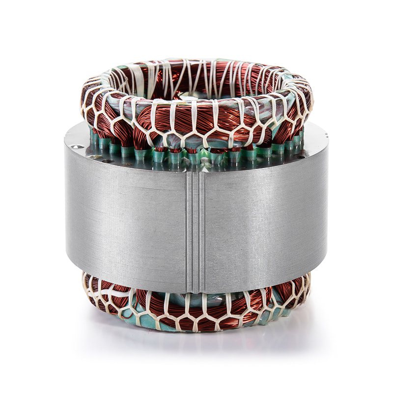
The stator core is the stationary part of the generator's magnetic circuit. It carries the alternating flux produced by the field and anchors the armature windings that convert that flux into electrical output. Because the flux reverses direction on every cycle, the core material experiences two losses that dominate the magnetic circuit: hysteresis loss and eddy current loss.
Hysteresis loss is the energy needed to re-magnetize the steel each cycle, and it scales with the area inside the material's B-H loop. Eddy current loss comes from voltages induced inside the core itself, which drive circulating currents that waste energy as heat. Laminating the core into thin, insulated sheets confines those currents to small cross-sections and cuts eddy loss roughly in proportion to the square of the lamination thickness. This is why generator stator cores are never made from solid steel.
The practical conclusion is that material selection should begin with core loss at the design frequency and flux density, then move through saturation behavior, workability, coating, and cost. For a 50/60 Hz generator, that sequence almost always lands on non-oriented silicon steel. Key properties worth putting into the specification:
- Specific total loss at rated frequency and flux density, in W/kg
- Magnetic permeability at the normal operating point
- Saturation flux density for overload and short-circuit capability
- Punching behavior, including burr tendency and die wear
- Coating quality and interlaminar insulation stability
Silicon Steel Remains the Reference Generator Stator Core Material
Cold-rolled non-oriented silicon steel, usually called CRNGO, is the default generator stator core material. Silicon content typically ranges from 2% to 3.5%. Silicon raises the electrical resistivity of iron, which directly reduces eddy current loss, and it also reduces magnetostriction, helping to quiet the machine. Above roughly 3.5% silicon the steel becomes brittle and hard to punch, which keeps most generator laminations at the lower end of the range.
Sheet thickness is the second control lever. For 50/60 Hz cores, 0.35 mm is the most common value, close to the 0.014 inch (29 gauge) figure used in older service literature. Cost-sensitive designs sometimes move up to 0.50 mm, while 400 Hz and variable-speed generators go down to 0.20-0.27 mm to keep eddy losses acceptable. Standard designations such as M400-50A and M530-50A follow the IEC convention in which the digits indicate maximum specific total loss in W/kg at 1.5 T and 50 Hz, which allows direct comparison between suppliers.
Laminations carry an insulating coating, typically an organic or inorganic C5 type, on one or both sides. That coating must survive stamping, stacking, and any welding or annealing, because interlaminar shorts create local eddy currents and hot spots. Coating systems and available grades continue to evolve, so it pays to follow industry news on motor core materials before freezing a design.
Specialty Materials for Demanding Duty Cycles
Silicon steel covers most generator requirements, but four alternative families come up whenever losses, weight, or operating frequency push beyond its limits. The table below summarizes how they compare at a practical level.
| Material family | Typical composition | Common thickness | Saturation flux density | Core loss at 50 Hz | Typical generator use |
|---|---|---|---|---|---|
| Non-oriented silicon steel | Fe + 2-3.5% Si | 0.20-0.50 mm | 1.8-2.0 T | Baseline | Industrial, standby, wind, and most mains-frequency generators |
| Cobalt-iron alloy | Fe + 49% Co | 0.10-0.35 mm | 2.3-2.4 T | Moderate; useful mainly at high flux density | Aerospace and high-power-density generator sets |
| Amorphous metal | Fe-Si-B ribbon | 0.02-0.03 mm | 1.4-1.6 T | Much lower than silicon steel | High-efficiency and high-frequency generator designs |
| Nickel-iron alloy | Fe + 48-80% Ni | 0.05-0.20 mm | 0.8-1.6 T | Low, but saturates earlier | Precision and instrument generators |
| Soft magnetic composite | Iron powder + binder | Net-shape part | 1.0-1.5 T | Low, especially at high frequency | Complex 3D flux paths and integrated structures |
Cobalt-iron alloys for compact, high-power machines
Cobalt-iron alloys, usually around 49% cobalt, provide the highest saturation flux density of any practical soft magnetic material, roughly 2.3-2.4 T. The same magnetic flux can therefore be carried through a smaller cross-section, which matters in aerospace and other weight-sensitive generator sets. Material cost is high and stamping is more difficult, so cobalt-iron appears mainly where power density justifies the premium.
Amorphous metal for minimum core loss
Amorphous metal is produced by ultra-fast cooling, leaving a non-crystalline structure with very low hysteresis and eddy losses, typically far below silicon steel. The trade-offs are practical: ribbon thickness is only around 0.025 mm, the material is hard and brittle, and conventional stamping is difficult, so cutting is often done by laser or water jet. Stacking factors are lower as well. Amorphous cores are chosen when the efficiency gain pays back quickly, such as high-efficiency wind or auxiliary generator designs.
Nickel-iron and soft magnetic composites for niche designs
Nickel-iron alloys (48% to 80% nickel) offer very high permeability and low loss at low flux density, which suits precision and instrument generators, but they saturate earlier than silicon steel. Soft magnetic composites, made from iron powder and a binder, allow near-net-shape parts with three-dimensional flux paths and low high-frequency loss, at the price of lower permeability and saturation. Both materials are selected for specific geometries more often than for general generator power stages.
Matching the Material to the Generator Application
Datasheet values only become meaningful when connected to the duty the generator will actually see. Three application families show how the material decision shifts in practice.
Industrial and standby generator sets
Mains-frequency industrial and standby sets almost always use 0.35 mm or 0.50 mm non-oriented silicon steel. Efficiency targets are balanced against material cost, and grades like M400-50A to M530-50A cover most requirements. What matters in this segment is repeatable quality at volume: consistent lamination geometry, controlled burr height, and stable stacking. Jufeng manufactures generator motor stator and rotor cores with in-house stamping and measurement to keep batch-to-batch behavior predictable.
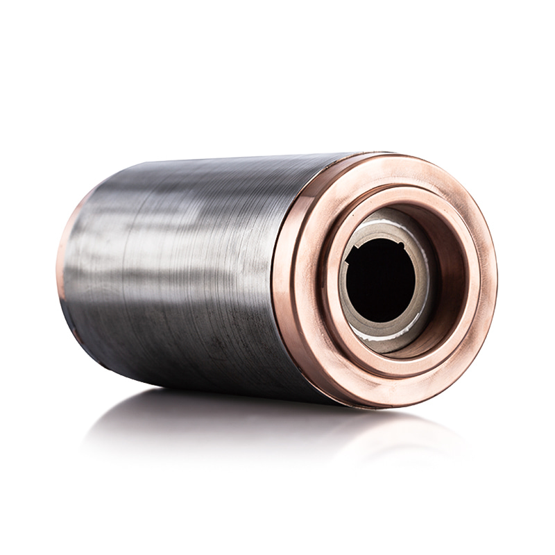
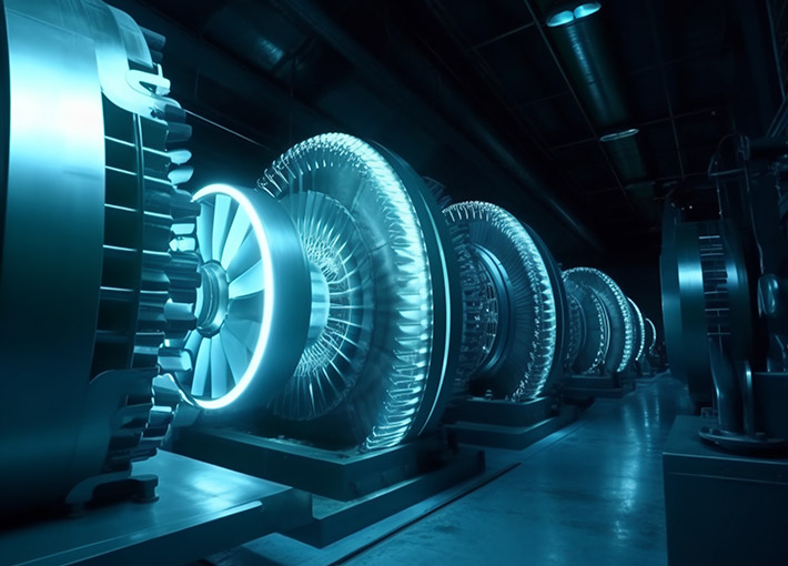 Custom Generator motor stator and rotor core Manufacturers, OEM/ODM SuppliersAs Generator motor stator and rotor core suppliers and OEM/ODM Generator motor stator and rotor core manufacturers in China, Zhejiang Juf...View Product →
Wind power generators
Wind turbine generators run at low speed with large diameters, so stator cores are assembled from very large laminations, and partial-load loss matters because turbines rarely operate at rated output. Material consistency is critical across thousands of sheets in one core. Insulated non-oriented steel remains the mainstream choice, with amorphous metal under evaluation for specific converter-driven topologies. Jufeng produces wind power generator motor stator and rotor cores with traceability from incoming coil to finished stack.
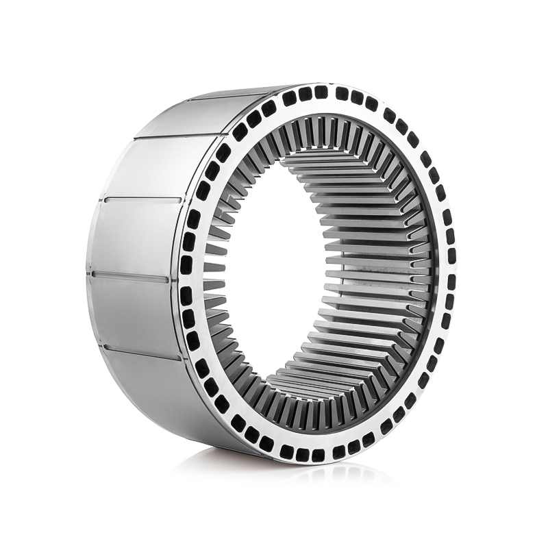
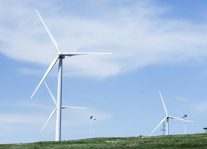 Wind Power Generator Motor Stator/Rotor Core Manufacturers, SuppliersZhejiang Jufeng is China Wind Power Generator Motor Stator/Rotor Core Manufacturers and OEM/ODM Suppliers, we custom Wind Power Generator...View Product →
EV generator motors
Vehicles that carry a dedicated generator motor, including range extenders, face high rotational speed, inverter-fed harmonics, and tight packaging. Thin-gauge silicon steel in the 0.20-0.27 mm range and coatings with high interlaminar resistance reduce harmonic loss, while cobalt-iron appears only in extreme high-performance prototypes. Production parts need progressive stamping dies with tight tolerances to hold geometry across long runs. Jufeng's EV generator motor stator and rotor cores are built for these higher-frequency conditions, where grade, coating, and stacking quality must be managed together.
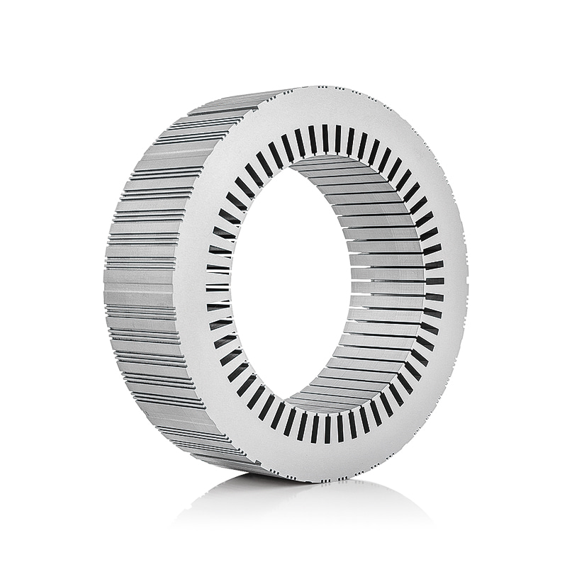
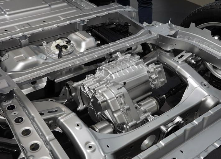 Electric Vehicle Generator Motor Stator/Rotor Core ManufacturersAs China Electric Vehicle Generator Motor Stator/Rotor Core Manufacturers and OEM/ODM Suppliers, Zhejiang Jufeng custom Electric Vehicle ...View Product →
Practical Sourcing Checks and Supplier Qualification
Once the material family and grade are fixed, the remaining risk sits in process quality. The following checks catch most problems found during prototype and pilot production.
Lamination thickness and stacking factor
Thinner laminations reduce loss but lower the stacking factor, the ratio of actual steel volume to apparent core volume. A well-built core typically reaches 0.95 to 0.98. When burr height on punched laminations climbs past roughly 0.05 mm, stacking factor and interlaminar insulation both start to degrade, increasing core loss and hot-spot risk.
Coating and interlaminar insulation
C5-type inorganic coatings tolerate stress-relief annealing and welding steps used during core assembly. After stacking and fastening by interlocking, welding, or bonding, the core still has to pass an interlaminar insulation check, because local shorts between sheets produce hot spots that can eventually damage winding insulation.
What to verify at the supplier
Ask how incoming material, stamping output, and finished cores are tested. Useful checks include:
- Burr height sampling, especially after die maintenance cycles
- Stacking factor measurement on production cores
- Core loss testing on ring samples or finished annular cores
- Interlaminar insulation resistance sampled across the stack
- Dimensional inspection of bore and outer diameter for final assembly fit
The stator core material decision couples electromagnetics, thermal design, and manufacturing economics. Silicon steel is the rational default for most generators; specialty materials should be adopted only when measured data shows a clear improvement for the specific duty cycle. And the supplier's stamping and testing discipline determines whether the grade's datasheet potential survives into the finished core. If you need to qualify a stator and rotor core supplier, contact Jufeng's engineering team with your operating frequency, flux density, and efficiency target, or review the full motor stator and rotor core product range to see how the same material and process controls apply across automotive, wind power, and industrial applications.
Previous article
How Stator Core Laminations Are Manufactured: Process, Materials & Quality Control
next article
Where is the stator core physically located within a motor assembly?
Related News
-
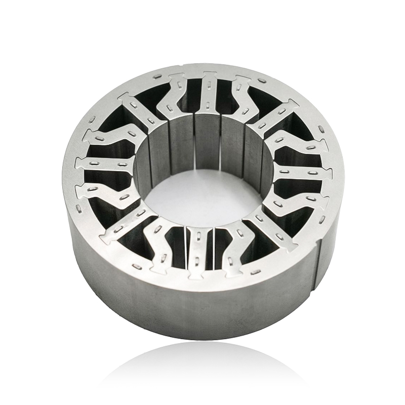
What are Stator and Rotor Cores? Stator Cores A stator core is the stationary component of an electric motor. It's the part that houses the copper windings, which, when an electric current passes thro...
See Details -
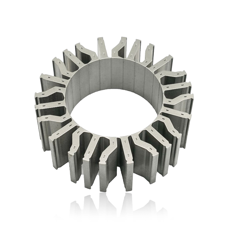
Introduction The modern automobile is a complex machine, and its evolution has been driven by continuous innovation in every component. While internal combustion engines have dominated the industry fo...
See Details -
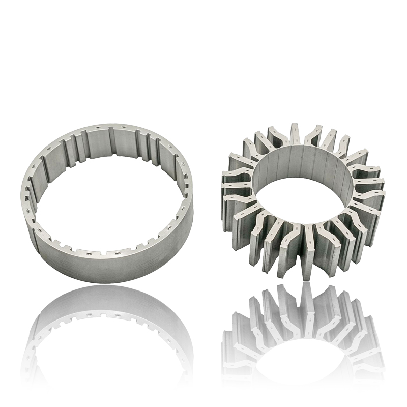
The Importance of Material Selection for Rotor and Stator Cores in Electric Vehicle Motors In the design of electric vehicle (EV) motors, material selection is a pivotal factor influencing the motor’s...
See Details -
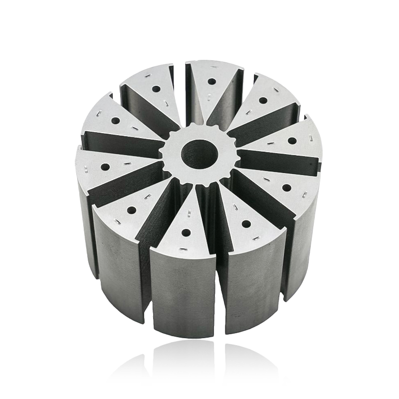
Introduction of automotive motor stator and rotor cores The increasing popularity of electric vehicles and hybrid electric vehicles has brought about significant advancements in automotive technology....
See Details


Zhejiang Jufeng Technology Co., Ltd. © All rights reserved
