 简体中文
简体中文 English
 русский
 Español
Inside Electric Machines — Design & Engineering
Where the Stator Core Actually Lives Inside a Motor
A quiet, fixed cylinder of steel does more work than most engineers give it credit for — sitting precisely between frame and rotor, holding the entire magnetic system in place.
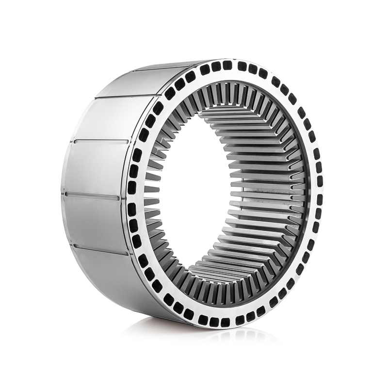
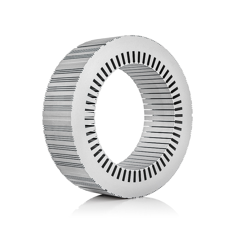
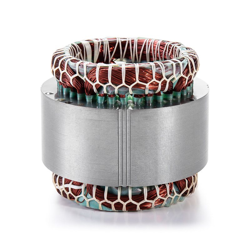
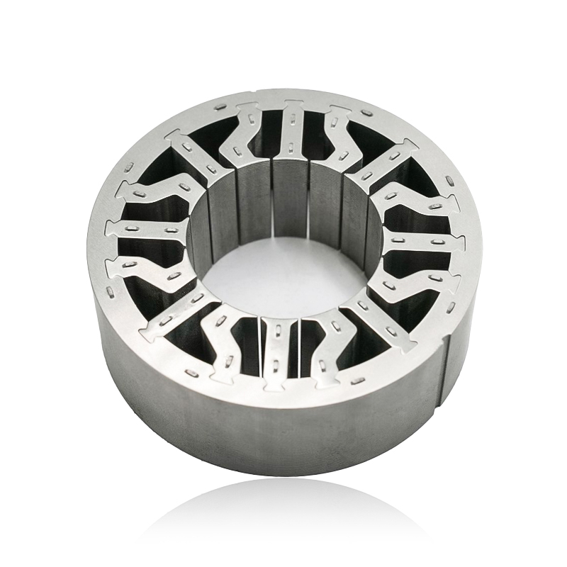
The stator core is the stationary cylindrical structure mounted inside the motor housing, surrounding the rotor with a narrow, carefully controlled air gap. It is fixed — pressed, shrink-fitted, or bolted — between the two end shields that carry the bearings and the rotor shaft. Whether inside an induction motor, a synchronous machine, or an AC generator, the stator core occupies the same conceptual position: the outer active magnetic layer, wrapped around a rotor it never touches, held rigid by a frame that never moves.
This placement is not incidental. The core must stay perfectly concentric with the rotor to preserve a uniform air gap — typically 0.3 mm in small motors and several millimeters in large industrial machines. A shift of even a fraction of a millimeter changes magnetic balance, vibration, and bearing life. So the stator core's location is treated less like packaging and more like a load-bearing design decision.
stator core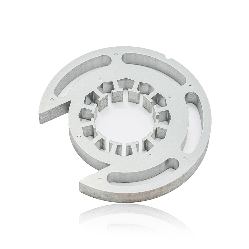
The Layered Anatomy of a Motor
Picture the motor as concentric rings, moving inward from the outside. Each ring carries a distinct mechanical or electromagnetic role — and the stator core sits at one very specific point in that sequence.
| Position | Component | Function |
|---|---|---|
| Outermost | Frame / Housing | Structural support, heat dissipation, mounting |
| Second layer | Stator core with windings | Fixed magnetic structure, holds windings in slots |
| Air gap | Narrow annular space | Free rotor rotation, magnetic flux transfer |
| Innermost | Rotor core & shaft | Rotating element producing mechanical output |
This sequence holds across almost every rotating machine type. In a motor stator core, the layer sits between frame and rotor; in a generator stator core, the same geometry applies in reverse energy flow — rotor motion induces current in the stationary windings rather than the stator driving rotation.
How the Core Is Held in Place
The stator core doesn't simply rest inside the housing — it's secured through one of several established methods, chosen by machine size and manufacturing scale.
- Press-fitting — the laminated stack is pressed into the frame bore under controlled interference, common in small and mid-size motors.
- Shrink-fitting — the frame is heated to expand, the core inserted, then cooled to clamp tightly; typical in larger industrial machines.
- Bolting or key-locking — large generator cores use keybars or dovetail slots welded into the frame, tolerating thermal expansion without shifting.
- Direct casting — in compact designs, the frame is cast around the core, fixing its position permanently.
Even a deviation of a few tenths of a millimeter in core position can create unbalanced magnetic pull — showing up later as noise, vibration, or premature bearing wear.
Position Relative to End Shields and Windings
The stator core spans the axial distance between the two end shields that cap the housing and support the bearings. Its axial position effectively defines where the rotor's active magnetic length must align. Shift the core even slightly along the shaft axis and the machine develops axial magnetic forces, pulling the rotor toward one end and loading the thrust bearing unevenly.
The windings themselves are not a separate mounted part — they're threaded directly into slots cut around the core's inner circumference. The core's slot geometry determines winding layout, insulation clearance, and cooling airflow, which is why "core" and "windings" are inseparable in practice even though they're distinct components on paper.
Info
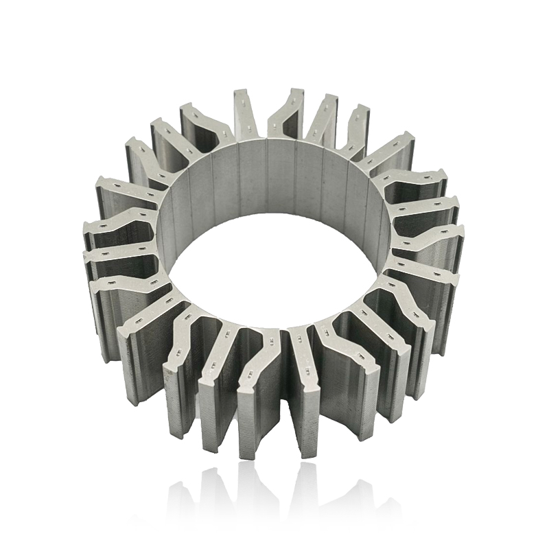
In outrunner or hub-motor designs, the arrangement inverts: the stator core sits on the inside, fixed to a central shaft, while the rotor rotates around the outside. The core is still stationary — only its radial position changes.
Why Position Affects Performance, Not Just Assembly
- Air gap uniformity — bore concentricity relative to the bearing seats governs torque ripple, noise, and efficiency.
- Heat transfer path — core-to-frame contact is often the primary route for conducting winding heat outward.
- Vibration and noise — a core that shifts under thermal cycling can generate magnetic noise at twice line frequency, a classic diagnostic signature.
- Serviceability — technicians rely on the core's fixed relationship to removable end shields when pulling a rotor for bearing work.
Warning
After any rewind or bearing replacement, always re-verify air gap and axial alignment before re-energizing. A core that looks correctly seated can still be off-center by an amount invisible to the eye but very audible once running.
Practical Inspection Checkpoints
| Checkpoint | What It Confirms |
|---|---|
| Air gap measurement (feeler gauge) | Core is centered around the full rotor circumference |
| Axial alignment check | Core stack aligns with rotor's active length, no thrust offset |
| Frame-to-core fit tightness | No looseness from shrink-fit relaxation or corrosion |
| Vibration spectrum analysis | Indirect indicator of core displacement or looseness |
Success
A properly seated core, confirmed by a uniform air gap reading and clean vibration spectrum, is one of the strongest indicators that a rebuilt or repaired motor will run reliably for years.
Danger
Never re-energize a machine after core reinstallation without confirming clearance around the full circumference. A displaced core can contact the rotor at startup, causing catastrophic winding and lamination damage.
In Summary
The stator core's location follows a consistent logic across nearly every rotating machine: fixed inside the outer frame, seated between the two end shields, wrapped around the rotor with a controlled air gap. Whether it's a motor stator core in an industrial pump drive or a generator stator core inside a power-plant alternator, the same layered architecture holds. Understanding exactly where it sits — and why that position matters — gives engineers and technicians a sharper instinct for diagnosing vibration, planning teardown, and specifying tolerances with confidence.