 简体中文
简体中文 English
 русский
 Español
Materials Engineering — Motor Design
A close reading of the numbers behind one of electrical engineering's quietest revolutions — and why a few tenths of a millimetre separate an efficient machine from a wasteful one.
The Direct Answer: Laminated Cores Cut Core Losses by 80–95% Compared to Solid Steel
A laminated core does not simply improve efficiency at the margins — it fundamentally changes the loss mechanism inside a rotating electrical machine. In practical terms, switching from a solid steel core to a laminated core built from thin, insulated silicon steel sheets typically reduces eddy current losses by 80% to 95%, depending on lamination thickness, operating frequency, and steel grade. For a mid-sized industrial motor running at 60 Hz, this can translate into an overall efficiency improvement of 3 to 8 percentage points, which is enormous when you consider that many premium-efficiency motor standards (such as IE3 or IE4) are decided by fractions of a single percentage point.
This is not a theoretical curiosity. It is the reason nearly every commercial induction motor, synchronous motor, and BLDC stator core assembly manufactured today uses stacked laminations rather than a machined solid billet. The efficiency gain is large enough that it dictates core material selection, manufacturing cost structure, and even the maximum practical operating speed of a machine.
Why the Loss Difference Is So Large: The Physics Behind the Numbers
When a magnetic field varies inside a conductive core, it induces circulating currents — eddy currents — that flow in closed loops perpendicular to the magnetic flux. In a solid steel core, these loops can be large, spanning the full cross-section of the material. Large loops mean large induced voltages and, because resistance is low across a big solid mass, very large circulating currents. Power dissipated as heat scales with the square of the current, so even a modest increase in loop size produces a dramatic increase in loss.
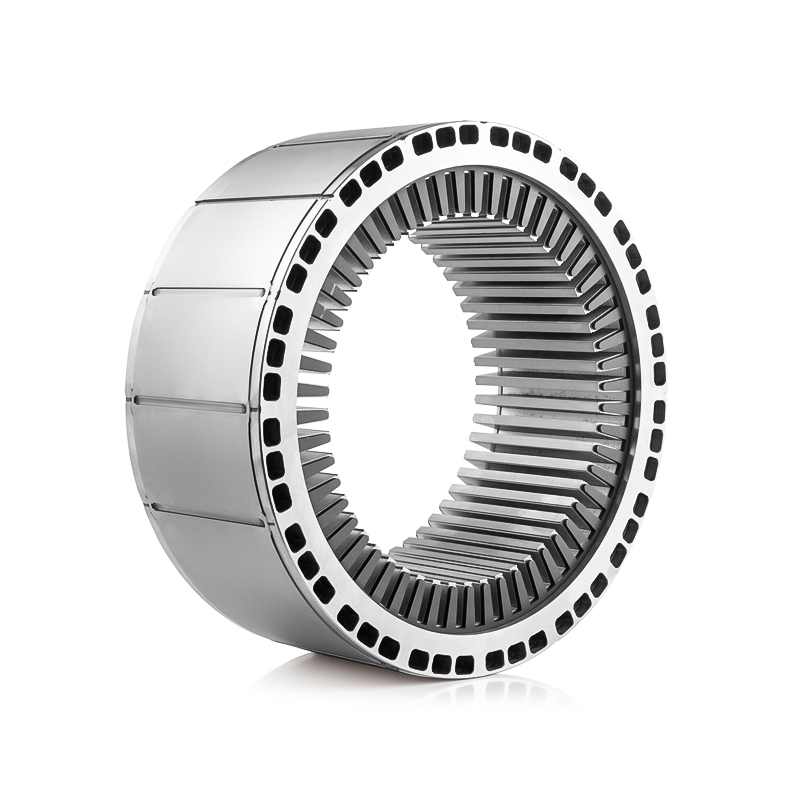
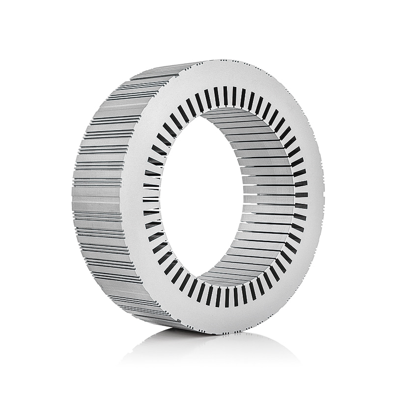
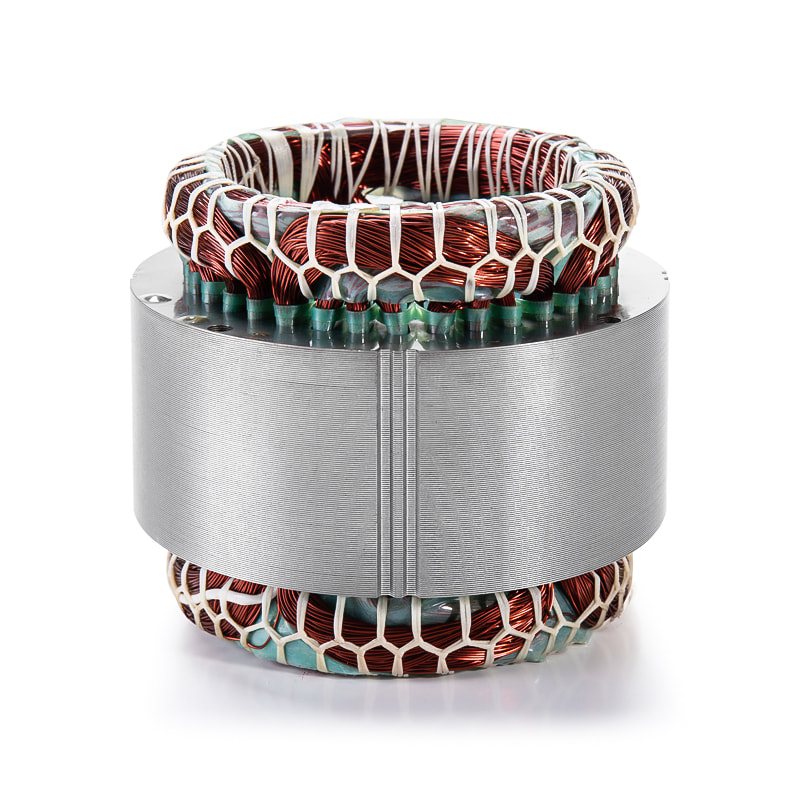
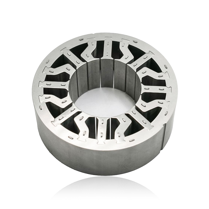
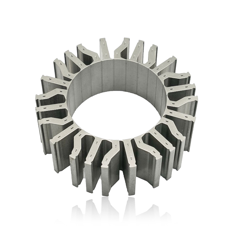
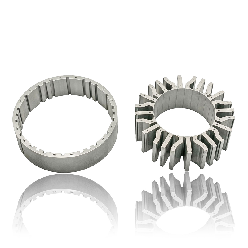
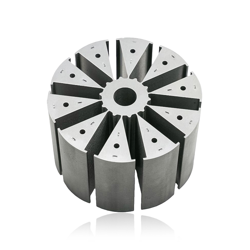
stator core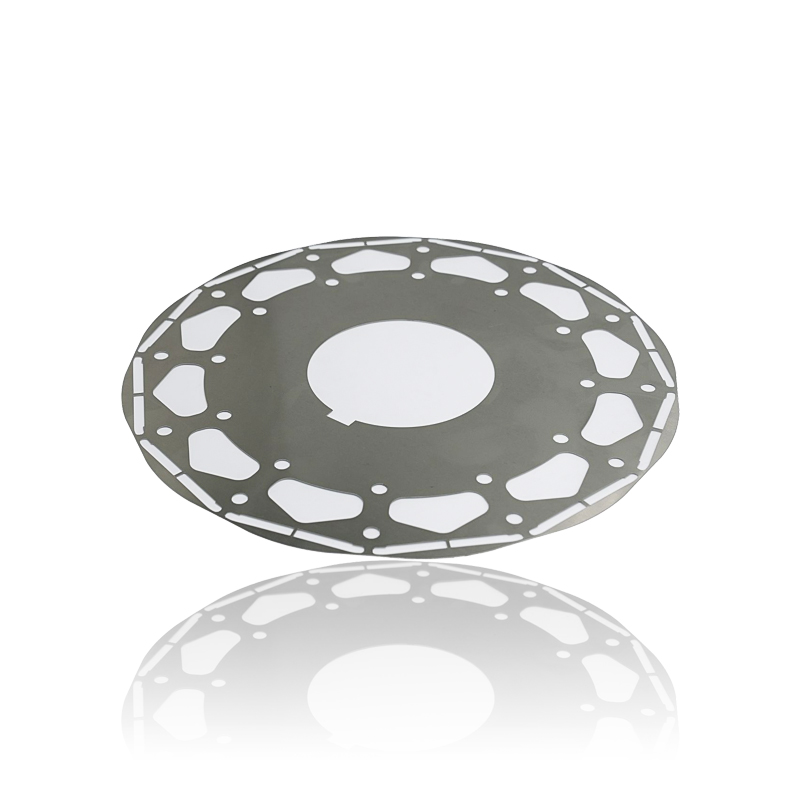
Lamination interrupts this process by physically dividing the core into thin sheets, each electrically insulated from its neighbors by an oxide layer or applied coating — forcing eddy currents into far smaller, far less destructive loops.
Since eddy current loss is proportional to the square of the lamination thickness, cutting sheet thickness in half reduces eddy current loss to roughly one-quarter of its previous value.
The Governing Relationship
Eddy current loss density is commonly approximated by the relationship:
Peddy ∝ (f² × Bmax² × t²) / ρ
where f is frequency, Bmax is peak flux density, t is lamination thickness, and ρ is the electrical resistivity of the steel. The squared dependence on thickness is the single most important factor explaining why even a modest reduction from, say, 0.65 mm to 0.35 mm sheets can nearly triple loss reduction.
Quantifying the Gap: Solid Core vs. Laminated Core Loss Data
Laboratory and field measurements across various rotor and stator geometries consistently show the same pattern: laminated cores dramatically outperform solid cores at power-line frequencies. The table below summarizes representative core loss figures for a comparable core volume operating at 60 Hz with a peak flux density of 1.5 T.
| Core Construction | Lamination Thickness | Approx. Core Loss (W/kg) | Relative Loss vs. Solid Core |
|---|---|---|---|
| Solid steel billet | N/A | 18–25 | 100% |
| Laminated, 0.65 mm sheets | 0.65 mm | 2.5–3.5 | ~14–17% |
| Laminated, 0.35 mm sheets | 0.35 mm | 1.0–1.6 | ~6–8% |
| Laminated, 0.20 mm sheets | 0.20 mm | 0.4–0.7 | ~2–3% |
This data illustrates why thinner laminations are the default choice in any application where efficiency, heat generation, or continuous duty operation matters. The reduction from solid steel to even relatively thick 0.65 mm laminations already eliminates over 80% of core loss, and moving to thinner high-frequency-grade sheets pushes that figure past 95%.
How This Translates Into Whole-Machine Efficiency
Core loss is only one component of total machine loss, which also includes copper (resistive) losses, friction and windage, and stray load losses. However, in machines where flux varies rapidly — including the stator of an induction motor and any BLDC stator core exposed to switching frequencies from an electronic drive — core loss can represent a significant share of total input power loss, sometimes 15% to 30% of all losses in a well-designed motor.
Consider a typical 10 kW industrial motor. If total losses at rated load are around 1,000 W, and core losses contribute roughly 250 W of that in a laminated design, an equivalent solid-core version could see core losses balloon to 1,500–2,000 W or more, since eddy current loss increases dramatically with core mass and frequency in an unlaminated structure. That single change could drop overall motor efficiency from a laminated design's typical 92–95% down to somewhere in the 75–85% range for an otherwise identical solid-core machine — a difference that would fail nearly every modern efficiency standard.
Where the Savings Are Most Pronounced
- High-frequency applications, since eddy current loss scales with the square of frequency
- Machines with high peak flux density, such as compact, high-torque-density motors
- Continuous-duty industrial motors where every percentage point of efficiency reduces energy costs over years of operation
- Variable-frequency drive systems where harmonic content increases effective core excitation frequency
Does the Efficiency Gain Scale With Frequency and Speed?
Yes, and this is one of the most important practical takeaways for anyone specifying a motor for a particular application. Because eddy current loss is proportional to frequency squared, the efficiency advantage of lamination grows as operating frequency increases. At 60 Hz line frequency, the gap between solid and laminated cores is already substantial. At the higher electrical and switching frequencies common in a modern motor stator core driven by variable-frequency inverters — often equivalent to several hundred Hz of effective flux variation — a solid core would suffer catastrophic losses, potentially exceeding the total power the motor is rated to deliver.
Info
This relationship is why high-speed machines, aerospace actuators, and BLDC stator core designs intended for high pole-count, high-RPM applications almost universally use thinner laminations, typically in the 0.20 mm to 0.35 mm range, rather than the thicker 0.5 mm to 0.65 mm sheets acceptable for standard 50/60 Hz industrial motors.
When Is the Efficiency Gain Not Worth the Cost?
Despite the clear efficiency advantage, laminated cores are not universally applied without tradeoffs. Lamination stamping, stacking, and insulation coating add manufacturing steps and cost compared to a machined solid core. In a small number of specialized applications, engineers accept the higher core losses of a solid rotor deliberately:
- Solid-rotor induction motors used in extremely high-speed turbomachinery, where mechanical robustness and simplicity outweigh the efficiency penalty
- Low-duty-cycle or intermittent-use equipment where energy cost savings would never offset the added manufacturing expense
- Certain hysteresis or eddy-current coupling devices that intentionally rely on induced currents to generate torque
Warning
For the overwhelming majority of motors, generators, and transformers, however, the efficiency return on investment from lamination is so large that solid cores are reserved only for niche mechanical or economic circumstances.
Practical Guidance for Selecting Lamination Thickness
For engineers and buyers evaluating core options, the decision usually comes down to balancing efficiency targets against cost and manufacturability. A few practical guidelines can help:
- Standard 50/60 Hz motors: 0.5 mm to 0.65 mm laminations are typically sufficient and cost-effective
- Inverter-driven or high-frequency machines: 0.35 mm laminations strike a good balance between loss reduction and stamping cost
- High-speed or premium-efficiency designs, including many BLDC stator core assemblies: 0.20 mm to 0.27 mm high-grade silicon steel is common
- Insulation coating quality matters as much as thickness — a degraded interlaminar coating can allow current to bridge sheets and partially negate the efficiency benefit
Danger
Degraded or damaged interlaminar insulation is not a cosmetic issue — it silently re-opens the large eddy current loops lamination was designed to eliminate, and can push a machine's core losses back toward solid-core territory even though the core still looks laminated on inspection.
Key Takeaways
Summary
The efficiency gained by using a laminated core instead of a solid one is not a marginal engineering refinement — it is a foundational design decision that separates viable, efficient rotating machines from impractical, heat-generating ones. Reductions in core loss of 80% to 95% are achievable simply by subdividing the core into thin, insulated sheets, with even greater relative gains at higher operating frequencies. For anyone specifying a motor stator core or evaluating rotor construction for a new machine design, lamination thickness and steel grade should be treated as primary levers for efficiency, not secondary manufacturing details. The data consistently shows that the modest added cost of lamination is returned many times over through reduced energy consumption, lower operating temperatures, and longer insulation life across the service lifetime of the machine.