
 简体中文
简体中文 English
 русский
 Español
Home / News / Industry News / The Role of Stator Core Laminations: Efficiency, Heat, Noise & Sourcing
The Role of Stator Core Laminations: Efficiency, Heat, Noise & Sourcing
Motor Core Engineering
The Thin Layers That Decide a Motor's True Efficiency
The role of stator core laminations goes beyond eddy-current control. It defines efficiency, heat, noise, and insulation life.
Give a motor designer a solid block of electrical steel, and they will explain why it cannot become a stator core. A structure with one continuous magnetic path and no joints looks ideal on paper, but it becomes a heater the moment the windings are energized. Almost every motor built today avoids this by assembling the stator core from thin, insulated steel layers called laminations. The concept sounds simple, yet the choices inside the stack, material grade, thickness, coating, stacking method, and dimensional consistency, decide whether a motor meets its efficiency target or quietly misses it.
Why a Solid Core Fails Where a Laminated Core Works
A laminated stator core exists for one primary reason: to interrupt the path of eddy currents. When alternating current flows through the windings, the magnetic field induces voltage in the steel core itself. In a solid core, that voltage drives circulating currents across the entire cross-section of the steel. These eddy currents follow the path of least electrical resistance, generate heat, and add directly to core loss.
The loss produced by eddy currents depends on the square of the thickness of the conducting path. Halve the thickness, and the eddy-current component of core loss drops to roughly a quarter. Lamination is therefore a geometric solution, not a metallurgical one. Each thin layer is separated from its neighbor by an insulating coating, so currents that would have flowed across a large area are confined to a small one.
Eddy-current loss is only part of the picture. Hysteresis loss comes from the energy required to flip magnetic domains on every magnetization cycle. Lamination does not eliminate hysteresis; material choice and stress management do. Together, the two mechanisms explain why thickness and chemistry both matter.
The role of stator core laminations is to contain eddy currents before they become heat. Every later decision about thickness, material, or coating refines that containment.
Thickness and Core Loss: The First Real Trade-Off
The most important specification on a lamination drawing is thickness, because it sets the ceiling for efficiency.
| Lamination thickness | Eddy-current behavior | Typical applications |
|---|---|---|
| 0.65 mm | Highest eddy-current loss among common grades | Large general-purpose induction motors |
| 0.50 mm | Balanced losses and mechanical robustness | Industrial motors, pumps, fans |
| 0.35 mm | Lower losses at 400 Hz to 1 kHz | Servo motors, generators, some EV traction |
| 0.20 to 0.25 mm | Lowest eddy-current loss, costlier, harder to stack | High-speed EV motors, aerospace, high-frequency machines |
The drawing specifies the starting material; the manufacturing process determines whether its magnetic potential survives. Two stacks of identical thickness can differ in core loss when one supplier produces larger burrs, applies a heavier coating, or controls annealing poorly.
Stacking factor is the ratio of actual steel length to measured stack length; 96 to 97 percent is normal for a well-made industrial stack. Lower numbers mean trapped air, lower torque, and wasted material.
Material and Insulation: The Second Half of the Story
Silicon steel for the magnetic path
Adding silicon to electrical steel raises electrical resistivity and reduces hysteresis loss, at the cost of a harder, more brittle material. Non-grain-oriented grades are standard for rotating machines; grain-oriented grades are mostly reserved for transformers and wound cores.
The coating that makes the stack work
Every lamination carries a thin insulating coating, classified in standards such as ASTM A976 as organic or inorganic. The coating must survive stamping, tolerate stacking, and often withstand a post-stamping anneal. When it is scratched or contaminated during punching, adjacent layers can short-circuit at the damaged spots.
Post-stamping annealing relieves mechanical stress from the punching die and restores permeability. It works only when the coating is specified to survive the anneal.
A burr a few micrometers high on a stamped tooth can make adjacent laminations touch at the edge. The result is a local eddy-current path that runs hotter and silently raises no-load loss.
Beyond Loss: Heat, Noise, and Consistent Geometry
Efficiency is the most common reason to use laminations, but a motor builder notices three other effects. A core with low losses generates less heat, which means a smaller cooling system and a better chance of meeting the insulation temperature class. A tightly compressed stack also behaves as a damped composite: inter-laminar interfaces absorb vibration energy, so a well-built core sounds quieter than a poorly stacked one.
Lamination is the cheapest loss-reduction technology a motor will ever use. No exotic materials, no novel winding; just thin steel layers, cut cleanly, insulated properly, and stacked consistently.
The third effect is dimensional consistency. Slot geometry, tooth width, and stack length directly define the flux distribution in the air gap. When thickness drifts outside tolerance, or stack pressure varies between batches, the torque curve shifts. For servo motors that need tight speed control, that shift is unacceptable.
How the Role Changes Across Applications
Electric vehicle drive motors
An inverter-driven EV motor sees magnetic flux harmonics at several kilohertz, and eddy-current losses grow with the square of frequency. EV stator and rotor cores therefore use thin material, typically 0.20 to 0.35 mm, with low-loss coatings that stay stable at high temperatures. Stack geometry and thermal performance matter as much as the steel grade.
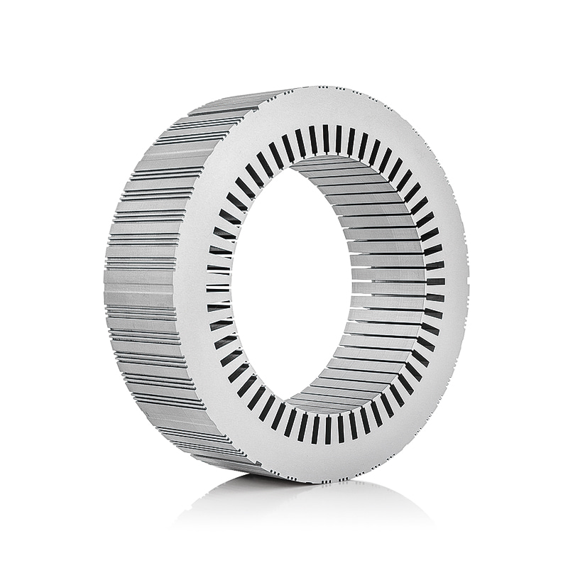
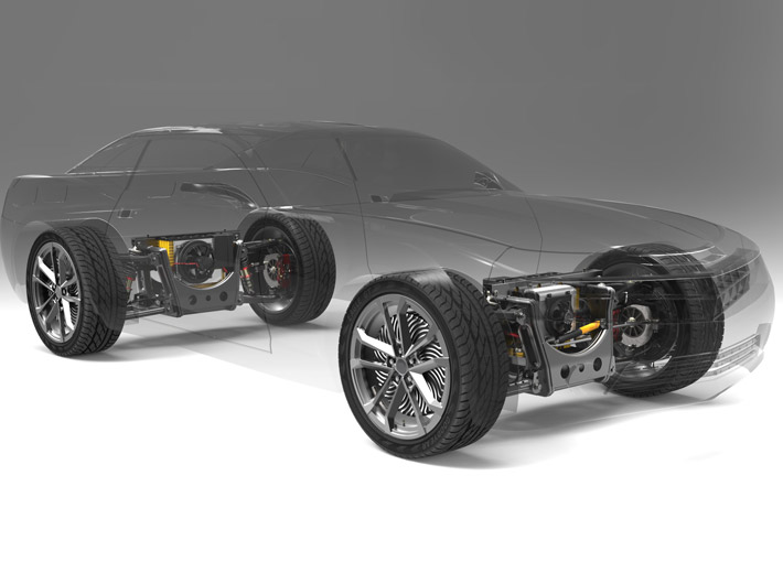 EV Drive Motor Stator and Rotor Core for High-Frequency OperationDesigned for inverter-driven EV motors, this stator and rotor core uses thin laminations and low-loss coatings to manage eddy-current losses at high frequencies. It suits engineers needing consistent thermal and electromagnetic performance in propulsion systems.View Product →
Industrial drive motors
At 50 or 60 Hz, the role becomes a balancing act between cost and performance across thousands of units. Standard 0.50 mm laminations with robust coatings are the common choice, and the real risk is batch-to-batch consistency. A supplier that holds tight tolerances and keeps burr height within the specified limit will produce stacks with repeatable losses, which directly affects efficiency class and warranty cost.
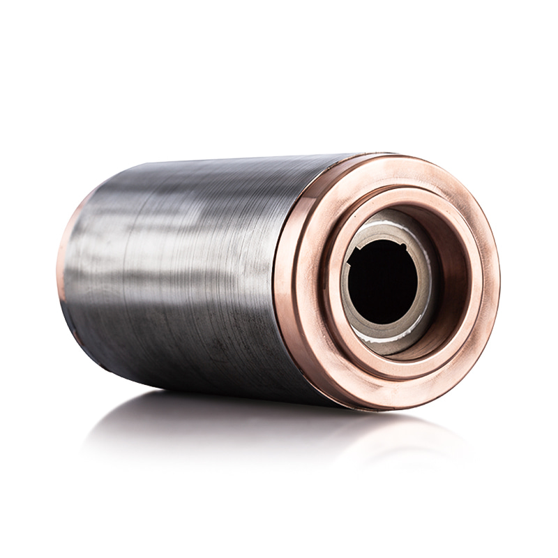
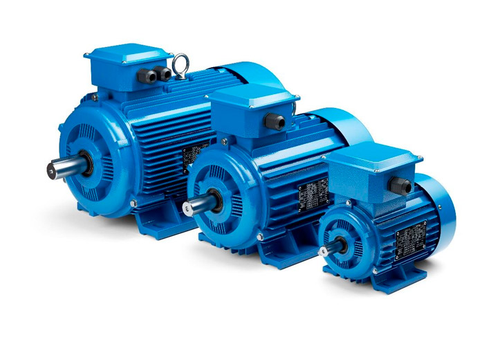 Industrial Drive Motor Stator and Rotor Core with Dimensional OptionsThis stator and rotor core range includes multiple rotor sizes, such as 49 mm, 106 mm, and 124 mm outer diameters, with copper rotors. It addresses the need for repeatable losses and tight tolerances at 50/60 Hz industrial applications.View Product →
Wind power generators
Large generator cores for wind turbines are measured in meters, and every radial segment must carry identical magnetic properties. Material flatness, coating durability against humidity and temperature cycling, and careful stack pressure control matter as much as the electromagnetic design.
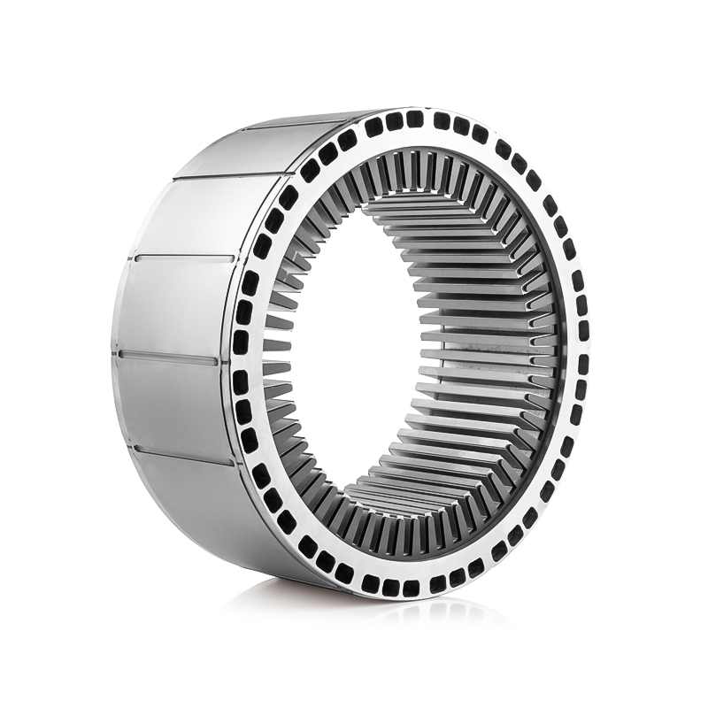
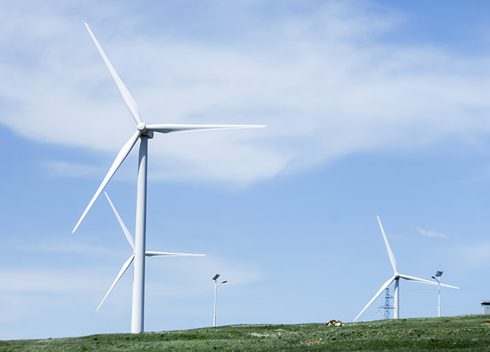 Wind Power Generator Stator and Rotor Core for Large-Scale TurbinesBuilt for wind turbines from 750 kW to 3.5 MW, this stator and rotor core uses laminated electrical steel with high permeability and low iron loss. Its design supports efficient energy conversion while handling humidity and temperature cycling.View Product →
What to Verify When You Source Stator Core Laminations
The design role of stator core laminations is decided on the drawing; whether the role is fulfilled is decided in manufacturing. These checks belong in supplier evaluation and incoming inspection.
- Material certificates that confirm the grade and guaranteed maximum core loss.
- Dimensional inspection covering slot geometry, tooth width, burr height, stack length, and parallelism.
- Stacking factor measurement to confirm that the effective steel length matches the drawing.
- Insulation integrity checks, including coating thickness and tests for continuity between layers.
- Process records for stamping speed, die maintenance, annealing, and handling that avoids edge damage.
A low quotation often hides one of three compromises: a lower material grade, looser geometric tolerances, or a shorter effective stack that looks correct on paper but leaves less steel in the core.
For a closer look at how these requirements are implemented on the line, our walk-through of how stator core laminations are manufactured covers blanking, stacking, and quality control.
A stator core specification is one part electromagnetics and two parts manufacturing honesty. Lamination keeps eddy currents under control; the stack quality decides whether that idea survives the stamping die. When steel grade, thickness, coating, and stack geometry are chosen together and verified, the motor rewards you with lower losses, a cooler winding, quieter operation, and a service life that matches the nameplate.
At Jufeng Technology, we manufacture motor stator and rotor cores for EV, industrial, wind, servo, and appliance applications, and we treat each lamination as a performance component. If you want to review your stack specification before committing it to production, talk directly with our engineering team.
Previous article
No more
next article
The Function of the Generator Stator Core: Flux, Support, Heat, and Vibration
Related News
-
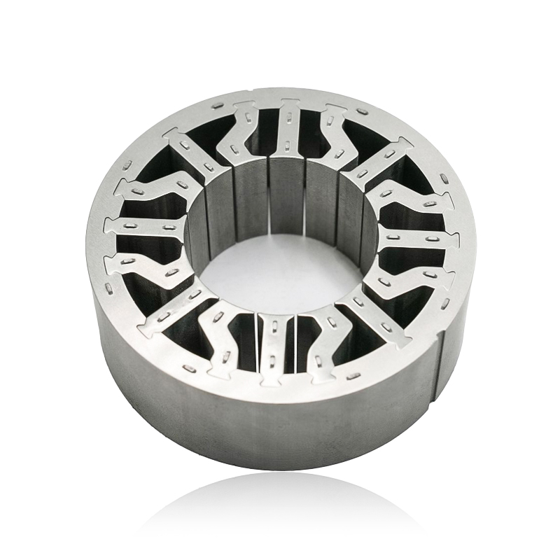
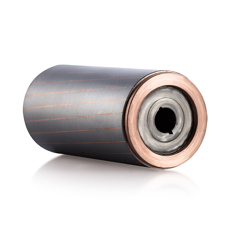
What are Stator and Rotor Cores? Stator Cores A stator core is the stationary component of an electric motor. It's the part that houses the copper windings, which, when an electric current passes thro...
See Details -
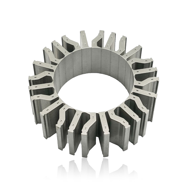
Introduction The modern automobile is a complex machine, and its evolution has been driven by continuous innovation in every component. While internal combustion engines have dominated the industry fo...
See Details -
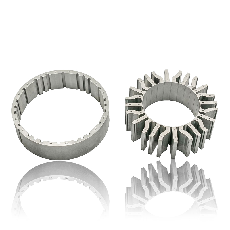
The Importance of Material Selection for Rotor and Stator Cores in Electric Vehicle Motors In the design of electric vehicle (EV) motors, material selection is a pivotal factor influencing the motor’s...
See Details -
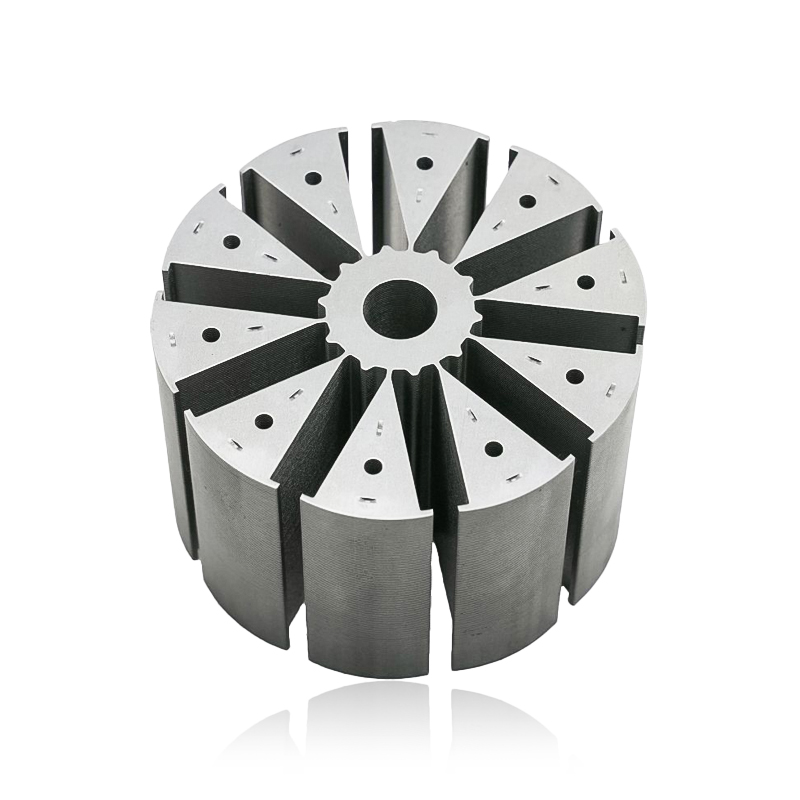
Introduction of automotive motor stator and rotor cores The increasing popularity of electric vehicles and hybrid electric vehicles has brought about significant advancements in automotive technology....
See Details


Zhejiang Jufeng Technology Co., Ltd. © All rights reserved
