
 简体中文
简体中文 English
 русский
 Español
Home / News / Industry News / Motor Rotor Core: How Laminations, Materials and Stacking Shape Performance
Motor Rotor Core: How Laminations, Materials and Stacking Shape Performance
Electric Motor Engineering
Inside the Motor Rotor Core: Where Thin Sheets of Steel Decide Performance
A motor rotor core looks like a plain stack of steel rings, yet its laminations, stacking method and tolerances quietly set the ceiling on efficiency, noise and service life. Here is how the part is built, and what buyers should demand from a supplier.
A batch of water-pump motors passes every bench test, yet field units come back running hot and drawing more current than the nameplate promises. Teardowns point, as they often do, to the same place: the rotor core.
The conclusion comes first. A rotor core is the component that turns electrical energy into torque, and small deviations in its material, lamination thickness or stacking show up immediately as heat, noise and lost efficiency. Everything that follows — what the part actually is, how it is made, and what should be verified before buying — flows from that fact.
What a Motor Rotor Core Actually Is
Every electric motor splits into a stationary part and a rotating part. The stator carries the windings that generate a rotating magnetic field. The rotor is the moving part, and the rotor core is its magnetic backbone: a cylindrical stack of thin electrical-steel sheets that carries flux across the air gap and turns it into torque.
A complete rotor assembly has three building blocks:
- The core itself, made of laminations insulated from one another by a microns-thin coating;
- The shaft, pressed into the center of the stack;
- The conductors or magnets, whether die-cast aluminum bars in a squirrel-cage induction rotor, magnets inserted into a permanent-magnet rotor, or copper windings in a wound rotor.
Precision with terms helps. A motor rotor core is not the whole rotor, and it is not the stator core, even though the two are usually stamped and stacked side by side in the same production flow. The rotor core carries flux; the conductors or magnets set into its slots interact with the stator field; and the air gap between the two cores — often less than half a millimetre in compact motors — is where torque is actually made.
Why the Core Is Built From Thin Laminations
If the core were machined from solid steel, alternating magnetic flux would induce swirling eddy currents inside it and burn energy as heat. Slicing the core into thin sheets and insulating each one breaks the paths those currents follow. This is the most important fact about rotor core construction, and it explains most of the cost and engineering behind the part.
Eddy Currents and Hysteresis
Two loss mechanisms dominate. Eddy-current losses fall as laminations get thinner. Hysteresis losses depend on the steel grade itself: non-oriented electrical steel with controlled silicon content is the standard choice because it magnetizes and demagnetizes efficiently, cycle after cycle. Thinner sheets and better grades both raise cost, so every specification is a deliberate compromise.
Info — A useful rule of thumb: the higher the electrical frequency a motor runs at, the thinner its laminations. Line-frequency appliance and pump motors commonly use 0.50 mm sheet, while high-speed traction and servo applications often move to 0.35 mm or 0.20 mm grades to keep eddy-current losses under control.
A rotor core is not a block of steel with slots cut into it. It is an engineered laminate — hundreds of insulated sheets, each positioned to a fraction of a millimetre, together forming the magnetic path that turns current into motion.
How a Rotor Core Is Manufactured
Stamping and Stacking
In volume production, rotor cores are born on a press. A progressive die feeds coil of electrical steel and punches rotor and stator laminations in sequence. Most modern lines use self-buckling interlocks, small coined joints in each sheet, so the stack bonds itself as it is punched, lamination by lamination, to a controlled stack height. Where interlocks are unsuitable, sections are joined by welding or cleating.
Cage Casting, Shaft Fitting and Balancing
For induction motors, the finished stack is often rotated slightly, lamination by lamination, to produce a skew that reduces torque ripple and magnetic noise, then die-cast with aluminum, or copper in demanding designs, to form the cage bars and end rings in one operation. The stack is press-fitted onto the shaft with a controlled interference fit and finally balanced so vibration stays within limits at operating speed.
Tolerances sit in the tenths of a millimetre throughout: slot geometry, burr height, stack squareness and bore diameter. This is why progressive-die maintenance and in-process optical inspection separate capable core suppliers from average ones.
Warning — Burr height is the quiet killer. Burrs above roughly 0.05 mm can pierce the insulation coating and short adjacent laminations, creating local heating that a finished-motor test bench will register as a symptom but never as a root cause.
Rotor Core Requirements Across Applications
A core that excels in a kitchen appliance would be wrong for a traction motor, and the reverse is equally true. The priorities below summarize how requirements shift across the applications Jufeng Technology serves.
| Application | Rotor core emphasis | What to confirm with the supplier |
|---|---|---|
| EV drive motors | Thin laminations of 0.35 mm or less, high stacking factor, accurate skew and magnet-slot geometry | Automotive quality system, PPAP-style documentation, steel-grade traceability |
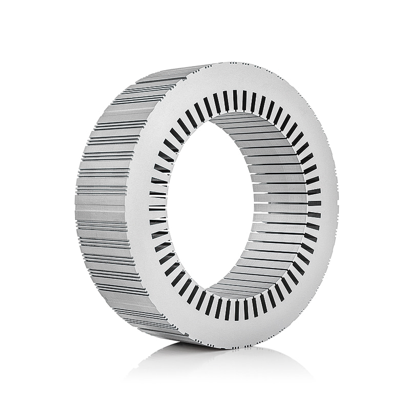
| Home appliance motors | Cost efficiency at high volume, 0.50 mm sheet, consistent burr control | Annual capacity, tooling life, batch-to-batch consistency data |
| Servo motors | Tight bore and stack tolerances, low torque ripple | Dimensional reports and capability data on critical dimensions |
| Wind power generators | Large-diameter laminations, robust welding or cleating, decades of service life | Material certification and joint-strength validation |
| Pumps and submersible motors | Reliable cage casting, coatings suited to harsh environments | Die-casting quality, coating class, shaft fit tolerances |
Two ends of that spectrum deserve a closer look. Electric vehicle drive motors sit at the demanding end, where thin high-grade laminations and disciplined stacking translate directly into driving range:
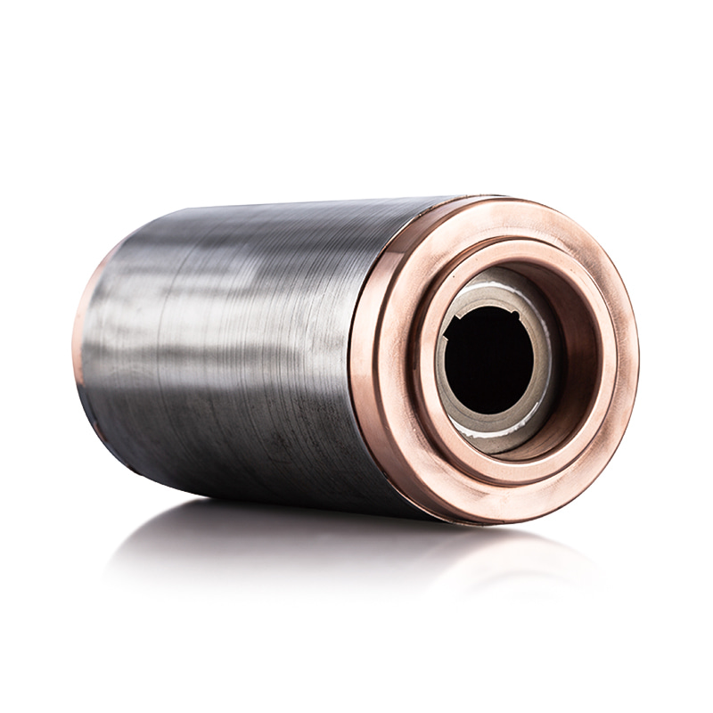
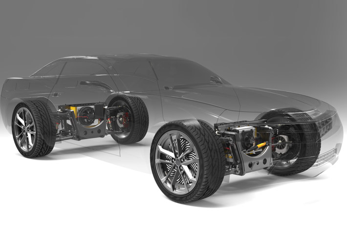 Electric Vehicle Drive Motor Stator and Rotor CoreBuilt from thin high-grade electrical steel laminations with rare-earth magnets and precise stacking, these EV drive motor cores improve efficiency and power density, directly translating disciplined lamination quality into driving range.View Product →
Wind power generators sit at the other end of the scale, where very large diameters and long, heavy stacks put a premium on flatness, joint integrity and mechanical strength:
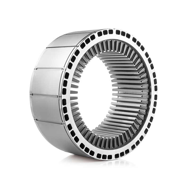
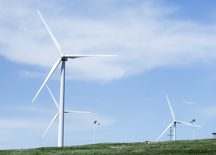 Wind Power Generator Stator and Rotor CoreLaminated electrical steel cores for wind turbine generators up to 3.5 MW, where large diameters and long, heavy stacks demand flatness, joint integrity, and mechanical strength for reliable energy conversion.View Product →
What Buyers Should Verify Before Sourcing
Rotor cores are cheap to quote and expensive to requalify. Before committing to a supplier, procurement and engineering teams should agree on a short checklist:
- Material certification: the exact steel grade, thickness and coating class, with mill certificates for each batch;
- Geometric evidence: dimensional reports covering bore, outer diameter, slot geometry, stack height and burr height, not just a drawing;
- Stack quality: measured stacking factor and interlock or weld integrity, verified on samples rather than claimed on paper;
- Process and quality system: press capacity, die maintenance practice, in-process inspection, and IATF 16949 certification for automotive programs;
- Engineering support: a willingness to co-develop tooling and iterate slot geometry with your motor design team.
Servo and other precision applications deserve particular care here, because tolerance drift that a fan motor would never notice becomes visible torque ripple in a positioning axis:
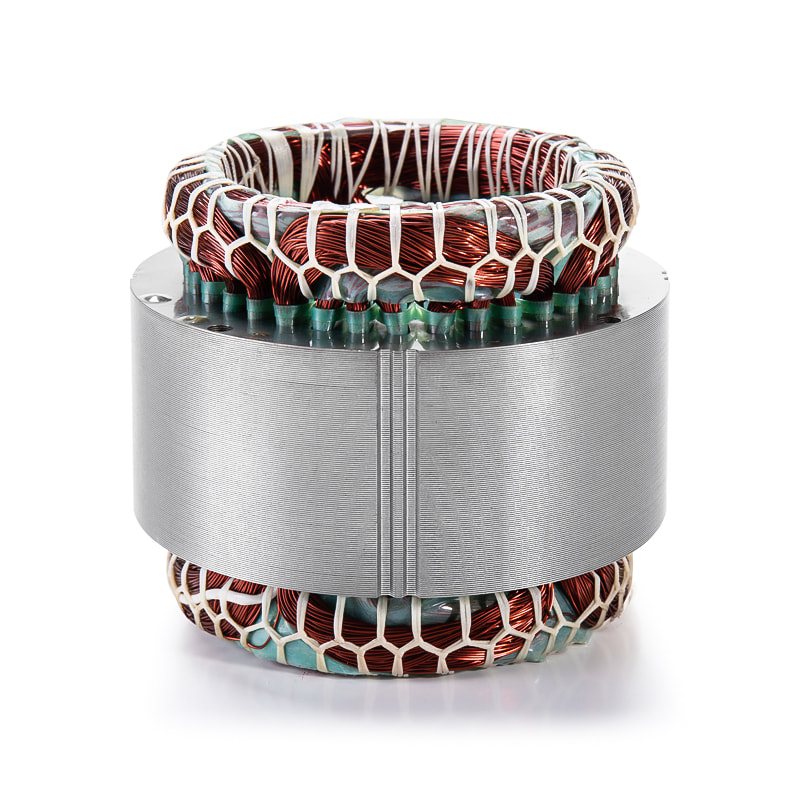
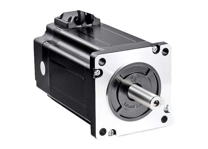 Servo Motor Stator and Rotor CorePrecision-manufactured servo motor cores with exacting tolerances minimize losses and heating, ensuring smooth, responsive control. Tight lamination consistency matters here because tolerance drift becomes visible torque ripple in positioning axes.View Product →
Danger — The most expensive rotor core is the one that gets silently respecified. If a supplier substitutes a lower-cost steel grade or a thicker lamination without formal change approval, efficiency can slip by a full percentage point or more, and the motors will still pass every electrical test at the end of the line.
Success — Ask a prospective supplier for a sample data package before the first order: material certificates, a dimensional report and a stacking-factor measurement. A supplier who produces one promptly for a trial will produce one reliably for years.
For teams planning an automotive program, the comprehensive guide to automotive motor stator and rotor cores on this site walks through material selection and design trade-offs in greater detail.
The rotor core rewards attention precisely because it hides. Nothing about it is visible on a finished motor, yet lamination thickness, stacking method and machining discipline decide how much of the electricity you pay for becomes useful work. Specify the core early, treat its tolerances as seriously as the winding design, and qualify suppliers on measured evidence rather than catalog claims.
Zhejiang Jufeng Technology Co., Ltd. supplies stator and rotor cores for applications ranging from EV drive motors, servo systems and wind generators to pumps, appliances and power tools, supported by in-house stamping, design and development, and measurement and testing capabilities. If you are evaluating a core supplier for your next motor program, you can start the conversation through our contact page.
Previous article
What Is a DC Motor Core? Laminations, Cored vs Coreless Motors, and Real Uses
next article
What Is a Motor Stator Core? Definition, Laminations, Losses and Manufacturing
Related News
-
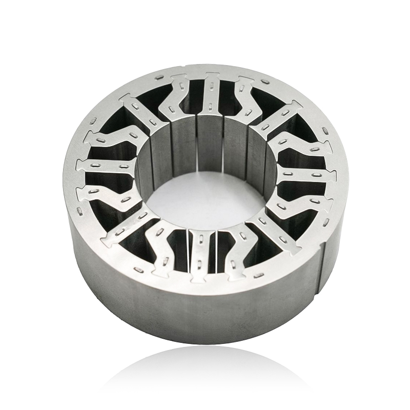
What are Stator and Rotor Cores? Stator Cores A stator core is the stationary component of an electric motor. It's the part that houses the copper windings, which, when an electric current passes thro...
See Details -
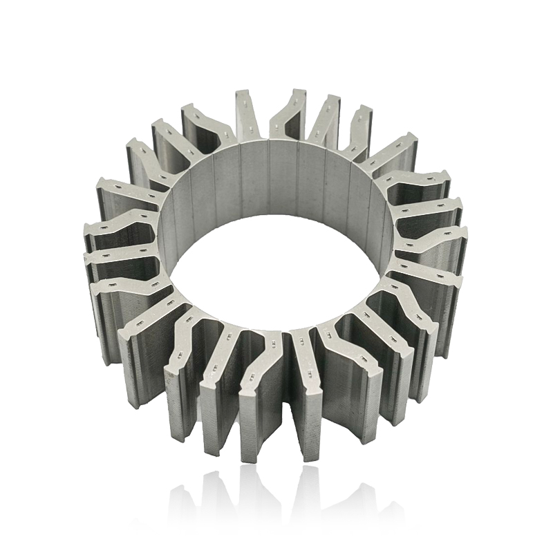
Introduction The modern automobile is a complex machine, and its evolution has been driven by continuous innovation in every component. While internal combustion engines have dominated the industry fo...
See Details -
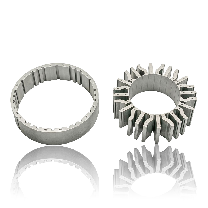
The Importance of Material Selection for Rotor and Stator Cores in Electric Vehicle Motors In the design of electric vehicle (EV) motors, material selection is a pivotal factor influencing the motor’s...
See Details -
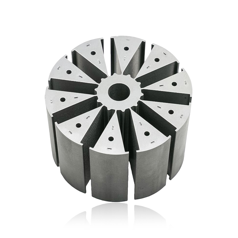
Introduction of automotive motor stator and rotor cores The increasing popularity of electric vehicles and hybrid electric vehicles has brought about significant advancements in automotive technology....
See Details


Zhejiang Jufeng Technology Co., Ltd. © All rights reserved
