
 简体中文
简体中文 English
 русский
 Español
Home / News / Industry News / What Is a Motor Stator Core? Definition, Laminations, Losses and Manufacturing
What Is a Motor Stator Core? Definition, Laminations, Losses and Manufacturing
What Is a Motor Stator Core?
The laminated steel heart of every electric motor — what it is made of, why it is stacked in thin sheets, and how it quietly decides efficiency, heat and noise.
A washing machine that hums instead of rattles, an EV that finds extra range in the same battery, a pump that stays cool through a desert summer — much of the credit in each case belongs to a part nobody sees. The stator core is the stationary magnetic structure inside an electric motor: a stack of thin, insulated electrical steel sheets punched with slots that carry the windings. It is where current becomes a rotating magnetic field, and in most machines it is the heaviest single component. Built well, the motor runs quiet, cool and efficient; built poorly, the losses return as heat, noise and wasted energy every operating hour. This guide explains what a stator core is, why it is laminated, how it is made, and what buyers should check before choosing a supplier.
What Exactly Is a Stator Core?
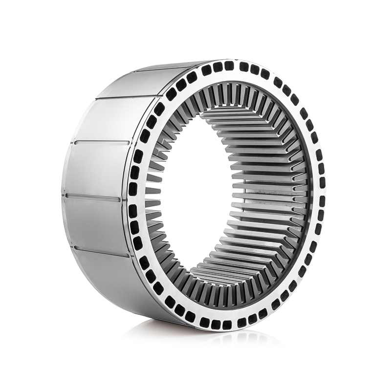
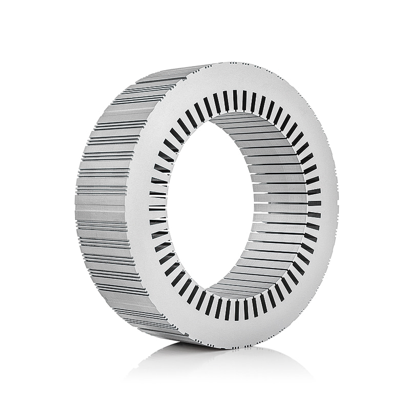
Every rotary electric machine has two essential parts: the rotor, which spins, and the stator, which stands still. The stator core is the magnetic structure inside that stationary part — a steel ring from a few centimetres across in a power-tool motor to well over a metre in a wind generator, with slots forming its inner wall and an outer rim, the yoke or back iron, closing the ring.
The core does three jobs at once:
- Teeth carry magnetic flux across the narrow air gap to the rotor.
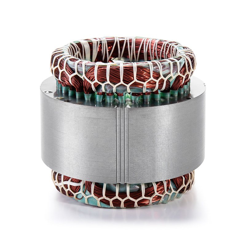
- Slots house and protect the copper windings.
- The yoke completes the magnetic circuit so that flux can loop back on itself.
The windings create the field, but the core concentrates and guides it. The same current flowing in copper without steel would produce only a fraction of the useful flux.
The copper creates the magnetic field, but the steel decides where that field goes — and how much of it is wasted as heat.
Why Thin Laminations Instead of Solid Steel
Because a solid core would waste energy as heat. Whenever the magnetic field changes, it induces circulating currents — eddy currents — inside the conductive steel. In one solid block those currents loop widely and dissipate as heat; in a stack of thin sheets, each separated from its neighbours by a micro-thin insulation coating, the loops are broken up and the loss collapses. Eddy-current loss falls roughly with the square of sheet thickness, which makes lamination the single most effective loss-reduction measure in motor design.
The standard material is non-oriented electrical steel with roughly 2–3% silicon. Silicon raises electrical resistivity, further taming eddy currents, and reduces hysteresis loss — the energy spent re-aligning the steel's magnetic domains on every cycle. Thinner, higher-alloyed grades cost more to buy and to stamp, so thickness is always an engineering trade-off:
| Sheet thickness | Typical motors | Why it is chosen |
|---|---|---|
| 0.50 mm | Industrial drives, pumps, fans, compressors | Lowest material and tooling cost; adequate at 50/60 Hz line frequency |
| 0.35 mm | High-efficiency appliances and generators | Better loss balance as speeds and frequencies climb |
| 0.20–0.27 mm | EV traction motors, high-speed spindles | Suppresses eddy loss where frequency reaches hundreds of Hz |
Info — stacking factor: the steel in a finished core occupies roughly 95–98% of its pressed height; the remainder is insulation and bonding gaps. A higher stacking factor means more effective magnetic cross-section in the same stack length, which is one more reason supplier process control matters.
How a Stator Core Is Manufactured
Almost every stator core in mass production is made by high-speed stamping and stacking. The principle is simple; the quality is decided in tolerances measured in hundredths of a millimetre:
- Slitting and blanking. Electrical steel arrives as coils and is slit to the width the lamination blank requires.
- Progressive-die stamping. A compound or progressive die punches the full lamination profile — bore, slots and interlock features — in a few strokes. Burr height is held to a few percent of sheet thickness, because burrs can pierce the insulation and short adjacent sheets.
- Stacking and joining. Laminations are stacked to length and joined by self-interlocking tabs, welding along the yoke, bonding varnish or rivets, each with different trade-offs in strength, loss and repairability.
- Stress-relief annealing. Punching work-hardens the steel and degrades its magnetic properties; annealing restores permeability and reduces loss.
- Sizing and inspection. The stack is compressed to final length — on precision motors within a few tenths of a millimetre — and bore geometry, slot shape and interlock strength are verified.
The tooling behind this is a serious investment: a progressive die for an automotive core may run millions of strokes, so design stability and volume commitments matter as much as unit price.
How the Core Shapes Efficiency, Heat and Noise
Efficiency and thermal margin
Iron loss — hysteresis plus eddy-current loss — is charged to the motor whenever it is energised, loaded or not, which is why core quality weighs heavily in appliances and EVs that spend thousands of hours at partial load. Better steel and thinner laminations also keep the windings cooler, and cooler windings last longer: insulation life roughly halves for every 10 °C of additional sustained temperature. The core is not only a loss source but a heat path — laminations conduct heat outward, and larger machine cores are split by vent ducts so cooling air can pass through.
Magnetic noise and vibration
Noise has a magnetic signature too. The core vibrates as the field pulsates, and the tonal whine of an accelerating EV is largely the core and its housing responding to electromagnetic forces. Bonding quality, slot geometry and skew all influence how much of that vibration reaches the ear.
Warning — insulation damage is permanent: overheating or a winding burnout can break down the coating between laminations. Shorted sheets behave like a solid block and losses climb steeply, which is why competent motor repair practice measures core loss after a burnout before investing in a rewind.
Automotive Cores: Higher Frequencies, Tighter Discipline
Electric vehicles push every stator-core problem harder. A traction motor spinning at 10,000–20,000 rpm multiplies the electrical frequency seen by the steel beyond line frequency, so EV stators use the thinnest laminations, and slot geometry must be precise enough to accept hairpin conductors at high slot fill. Volume adds another layer: automotive cores are stamped by the million, so batch-to-batch consistency — interlock strength, stack length, burr height — is audited as rigorously as the design itself. The same discipline applies to the small motors throughout a car — window lifts, coolant pumps, actuators — and to the generator motors that work alongside the drivetrain.
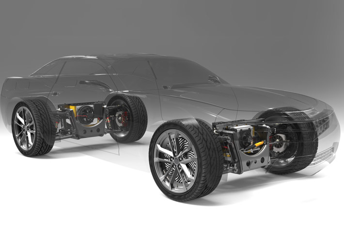 Electric Vehicle Drive Motor Stator and Rotor Core SuppliersEV traction motors running at 10,000–20,000 rpm require the thinnest laminations, precise slot geometry for hairpin windings, and audited batch consistency, making a qualified stator and rotor core supplier essential for high-volume drive programs.View Product →
Beyond the Car: Industrial, Energy and Appliance Cores
Outside the vehicle market the same physics serves a much wider spread of machinery, and each field stresses a different requirement. Appliance motors are optimised for cost at line frequency; servo motors demand precise, repeatable response and very consistent tooth geometry; industrial drives and fans run for decades, so long-hour efficiency dominates. Water pumps and electric submersible pumps in oil wells need compact cores that survive harsh environments, while elevator traction and rail transit motors carry safety-critical loads. At the far end of the size range, wind-power generator cores exceed a metre in diameter and are commonly built in segments so they can be transported and serviced. The breadth of applications can be seen in the non-automotive motor stator and rotor core range:
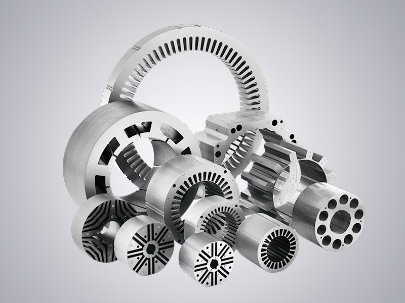 Non-Automotive Motor Stator and Rotor Cores ManufacturersFrom appliance and servo motors to pumps, elevator traction, rail transit, and segmented wind-power generator cores, this range covers the diverse efficiency, precision, and durability requirements of industrial motor applications.View Product →
What to Check Before You Source a Stator Core
For a purchasing team, a stator core looks like a simple quote: a steel ring with slots. In practice the risk hides in the material certificate and the process data. A capable supplier should document the electrical steel grade, thickness and insulation coating for every batch, commit to a written burr-height limit, report stacking factor and stack-length tolerance, and own its tooling, measurement and core-loss testing in house rather than subcontracting the steps that decide quality.
Success — a short, effective audit list: ask for material certificates matched to heat numbers, a core-loss test report on finished stacks, dimensional reports against the drawing, and the supplier's tooling-maintenance plan across the programme life. Suppliers who answer those four items precisely rarely disappoint at volume.
Design engineers weighing materials and quality checkpoints for a vehicle programme will find a fuller treatment in our guide to automotive motor stator and rotor core design, materials and key considerations, and the Jufeng Technology engineering team can discuss specific projects through the contact page.
In Short
A motor stator core is the laminated, stationary magnetic structure that turns winding current into a directed rotating field. Thin, insulated sheets of silicon steel keep eddy and hysteresis losses low; precise stamping, stacking and annealing decide whether the finished core delivers the efficiency, thermal margin and quiet running the motor was designed for. Whether the machine is a refrigerator compressor or a high-speed traction motor, the core is where material selection and manufacturing discipline show up first — and where a well-chosen manufacturing partner pays for itself over the life of the programme.
Previous article
Motor Rotor Core: How Laminations, Materials and Stacking Shape Performance
next article
Why Is a Stator Core Made of Laminated Steel? Eddy Current Loss Explained
Related News
-
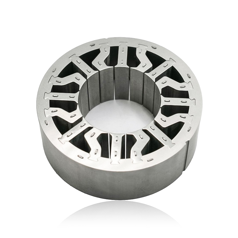
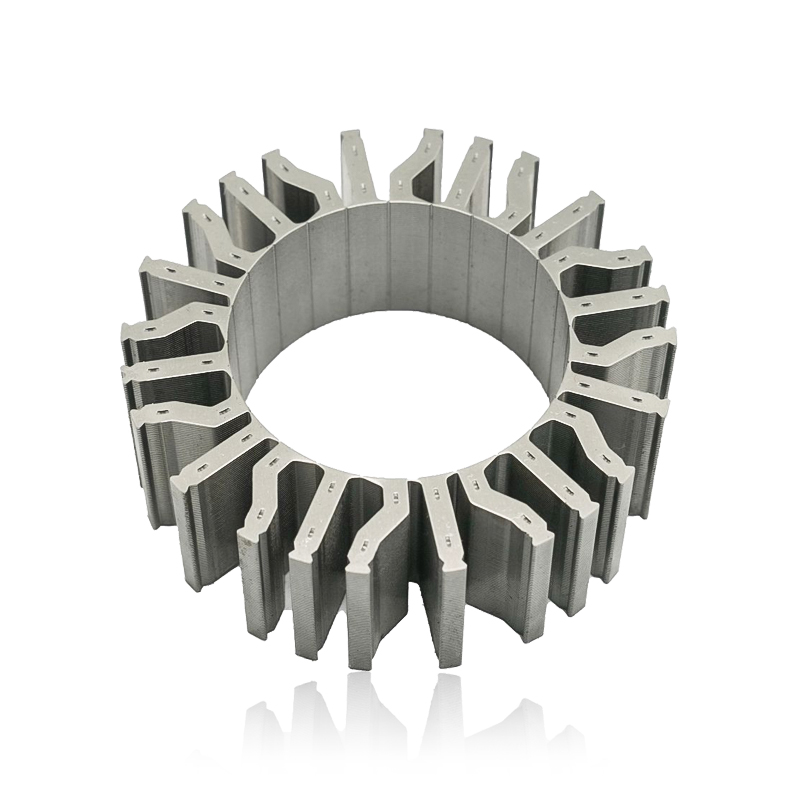
What are Stator and Rotor Cores? Stator Cores A stator core is the stationary component of an electric motor. It's the part that houses the copper windings, which, when an electric current passes thro...
See Details -
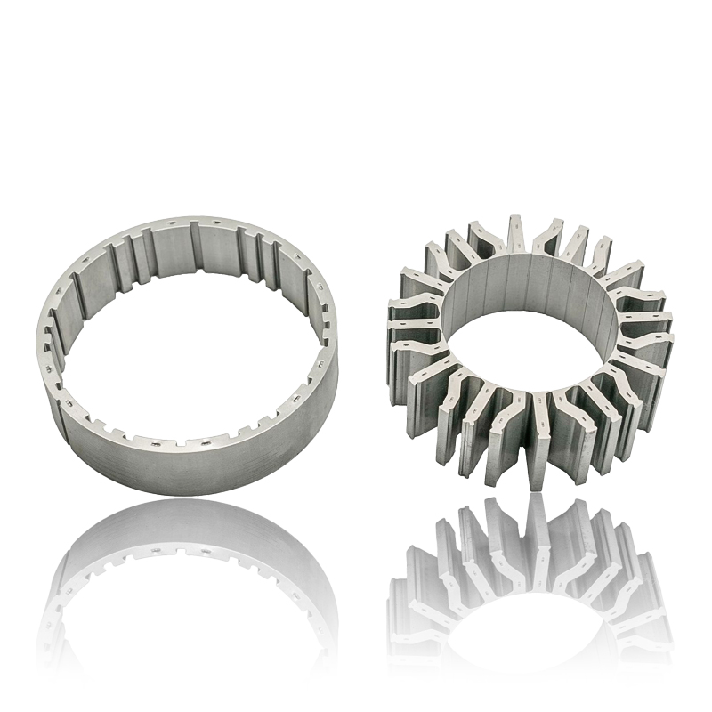
Introduction The modern automobile is a complex machine, and its evolution has been driven by continuous innovation in every component. While internal combustion engines have dominated the industry fo...
See Details -
The Importance of Material Selection for Rotor and Stator Cores in Electric Vehicle Motors In the design of electric vehicle (EV) motors, material selection is a pivotal factor influencing the motor’s...
See Details -
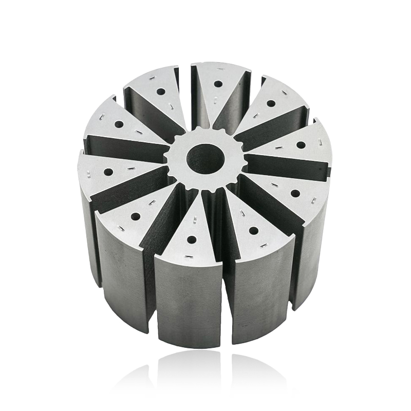
Introduction of automotive motor stator and rotor cores The increasing popularity of electric vehicles and hybrid electric vehicles has brought about significant advancements in automotive technology....
See Details


Zhejiang Jufeng Technology Co., Ltd. © All rights reserved
